
Running one brushless motor from a microcontroller is already enough to make a workbench look like a tiny robotics lab. Running four brushless motors with a single Pi Pico? That sounds like the kind of thing that begins as a weekend experiment and ends with someone saying, “Why is there a propeller mark on the cardboard box?”
Yet the idea is not magic, and it is not only for drone engineers wearing oscilloscope probes like jewelry. A Raspberry Pi Pico, built around the RP2040 microcontroller, has enough real-time hardware muscle to coordinate multiple motor-control signals when the design is planned carefully. The trick is understanding what the Pico should do, what external motor-driver hardware must do, and where software choices such as MicroPython, C, PWM, PIO, Hall feedback, PID loops, and field-oriented control fit into the picture.
This article explains how a single Pi Pico can control four brushless DC motors, why the project is technically impressive, where the bottlenecks appear, and what makers can learn from it. We will keep the tone friendly, because motors are already spinning fast enough without the article also trying to sound like a graduate thesis in a lab coat.
What Does It Mean to Run Four Brushless Motors From One Pi Pico?
First, let’s clear up a common misunderstanding. The Pi Pico does not directly power four brushless motors. A Pico GPIO pin is not a tiny superhero in a cape. It can send logic-level control signals, but it cannot dump amps of current into motor windings. For that, the system needs power electronics: a three-phase motor driver, an ESC, MOSFET stages, current sensing, protection circuitry, and a suitable power supply.
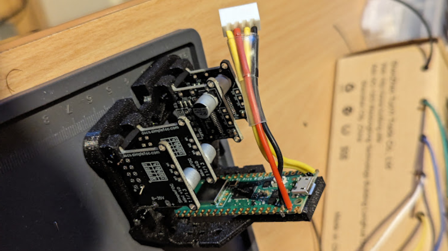
In the project that inspired this discussion, the maker used the Pico as the brain and motor-driver hardware as the muscle. The motor driver handled the high-current switching needed by each three-phase brushless motor. The Pico generated timing, commutation, feedback processing, and control decisions. In other words, the Pico was not “pushing the car”; it was telling the driver exactly when to press the pedals.
Why the Pi Pico Is Surprisingly Good at This Job
The Raspberry Pi Pico is inexpensive, small, and famously approachable. But under that humble board is the RP2040, a dual-core microcontroller with flexible timing features. For motor control, the big attraction is not just CPU speed. It is the combination of PWM channels, predictable timing, and Programmable I/O, usually called PIO.
PIO is one of the RP2040’s best party tricks. It allows small state machines to handle precise input and output patterns without constantly bothering the CPU. That matters because motor control is timing-sensitive. If your code pauses at the wrong moment because it is busy printing debug text, calculating a floating-point operation, or emotionally processing a semicolon error, the motor will not patiently wait.
PWM Channels and Motor Signals
Brushless motor control often depends on pulse-width modulation, or PWM. PWM rapidly switches an output on and off, changing the duty cycle to control effective voltage or signal timing. In simple ESC-style control, PWM may look like servo-style throttle pulses. In lower-level motor-control designs, PWM controls the phases of the motor through a driver stage.
The original Pico offers multiple PWM outputs, and the RP2040 PWM system is arranged in slices. Each slice can provide two outputs sharing the same base frequency while allowing different duty cycles. For many robotics and motor projects, that is plenty of flexibility. But when four brushless motors are involved, especially with feedback and synchronized updates, the design quickly becomes more interesting than blinking an LED.
PIO: The Secret Sauce
PIO helps because it can create deterministic waveforms and read timing-critical signals. For example, it can assist with PWM generation, encoder reading, Hall sensor timing, or other repetitive signal-handling chores. That frees the main CPU cores to run control loops, filter sensor readings, calculate speed, and adjust torque commands.
This is where the Pico starts to feel less like a “cheap microcontroller board” and more like a compact real-time control platform. It will not replace a dedicated industrial motor controller in every situation, but for maker-grade robotics, gimbals, small electric mechanisms, and educational projects, it punches well above its price.
The Role of Motor Driver Hardware
A three-phase brushless DC motor needs controlled current through its three windings. The Pico cannot do that directly, so the system requires motor-driver ICs or external ESCs. In the referenced build, a TI DRV8313-style three-phase driver is the kind of part that makes sense for compact BLDC applications. It provides three half-bridge outputs intended for driving a three-phase brushless motor, while also offering protection features useful in real hardware.
Think of the motor driver as the electrical bouncer at the club. The Pico politely says, “Please energize phase A now.” The driver says, “I will handle the big current, the heat, and the angry electrons.” Everyone stays happier that way.
Why One Driver Is Not Enough for Four Motors
Each three-phase BLDC motor needs its own three-phase output stage. So, running four motors means four sets of driver circuitry. The clever part is not that one driver chip powers four motors. The clever part is that one Pi Pico coordinates four motor controllers or driver stages.
This distinction matters for readers planning their own build. A Pico can send the control signals, calculate feedback, and update duty cycles. But every motor still needs a properly rated power stage, power supply capacity, heat management, and protection. If you skip that part, your project may become a smoke machine, and not the cool concert kind.
MicroPython vs C: Where the Bottleneck Shows Up
MicroPython is wonderful for learning, prototyping, and making hardware do something useful before your coffee gets cold. It is clean, readable, and beginner-friendly. For basic PWM output, reading a potentiometer, or controlling a single ESC, MicroPython is often more than enough.
But advanced brushless motor control is a different animal. Field-oriented control, fast feedback loops, Hall sensor processing, speed estimation, torque limiting, and four simultaneous motors create a workload where interpreter overhead becomes noticeable. That is why many serious Pico motor-control experiments eventually move from MicroPython to C or C++.
C gives lower overhead, tighter timing, more predictable execution, and closer access to the hardware. It also gives you more opportunities to stare at compiler errors with the quiet dignity of a person questioning their life choices. Still, for multi-motor control, C is usually the right move.
Understanding Brushless Motor Control
A brushed DC motor is relatively simple: apply voltage, and it spins. Reverse polarity, and it spins the other way. A brushless DC motor is more efficient and durable, but it needs electronic commutation. The controller must energize motor phases in the right order at the right time.
There are several ways to do this, ranging from basic six-step commutation to more advanced field-oriented control. The best choice depends on the project’s goals. A fan, a gimbal, a robot joint, and a quadcopter motor may all use brushless motors, but they do not need the same kind of control.
Six-Step Commutation
Six-step commutation is one of the simpler methods. It energizes motor phases in a sequence based on rotor position. It is common, practical, and easier to implement than full FOC. With Hall sensors, the controller can detect rotor position and switch phases accordingly. This method can work well for many applications, though it may produce more torque ripple and acoustic noise than smoother control methods.
Field-Oriented Control
Field-oriented control, often shortened to FOC, is more elegant. It mathematically transforms the motor-control problem into something similar to controlling a DC motor. Instead of simply stepping through phase states, FOC attempts to control the magnetic field and torque-producing current more smoothly.
The payoff is smoother motion, better torque control, improved efficiency, and more refined behavior at low speeds. The cost is complexity. FOC requires fast calculations, accurate rotor position information, careful timing, and a control loop that does not wander off like a distracted squirrel.
Hall Sensors, Feedback, and Closed-Loop Control
Running four motors open-loop is one thing. Running four motors with feedback is much more useful. Hall sensors can tell the controller where the rotor is, allowing the Pico to commutate the motor more intelligently and estimate speed. With feedback, the system can implement speed control, torque limiting, and PID loops.
A PID controller compares the target value with the measured value and adjusts output based on proportional, integral, and derivative terms. In plain English: it tries to correct errors without overreacting like someone discovering a typo after publishing a blog post.
For four motors, feedback also helps with matching behavior. If one motor is under more load than another, closed-loop control can compensate. This is important in robotics, small vehicles, camera stabilizers, and experimental platforms where balanced motion matters.
How One Pico Can Handle Four Motors
The practical strategy is to divide responsibilities. Time-sensitive waveform generation can be handled by PWM hardware or PIO. Sensor inputs can be captured using GPIO interrupts, PIO, or carefully timed routines. The main CPU code can run control loops at a defined frequency, update target commands, and manage safety limits.
A simplified architecture might look like this:
- Four BLDC motors, each connected to a suitable three-phase driver stage.
- Hall sensors or position feedback lines from each motor.
- PIO state machines or hardware PWM generating accurate control waveforms.
- C code running speed or torque loops.
- Current, temperature, or fault monitoring where supported by the driver hardware.
- A power supply sized for the combined current draw of all motors.
The biggest challenge is not merely “having enough pins.” It is coordinating timing, computation, feedback, and power behavior so the system stays stable. Four motors multiply the little problems. One noisy sensor line becomes four chances for weirdness. One tuning issue becomes a quartet of tiny mechanical comedians.
Power, Heat, and the Part Nobody Should Ignore
Motor projects are often introduced with code, but power design decides whether the project survives. Four brushless motors can draw serious current, especially during startup, sudden acceleration, stalls, or load changes. The motor driver must be rated for the voltage and current. The PCB layout must handle current paths. The supply must avoid sagging. The wiring must be secure. Heat must have somewhere to go.
Even small motors can surprise you. A motor that looks harmless on a desk can become a high-speed finger-finder when it spins up. For testing, remove propellers, clamp motors securely, use current-limited supplies when possible, and keep loose wires away from rotating parts. Safety is not the boring chapter. It is the chapter that keeps the next chapter from being titled “Why My Desk Has a Burn Mark.”
Where This Approach Makes Sense
Running four brushless motors from one Pi Pico is useful for more than showing off. It can fit several real projects:
Small Robotics Platforms
A four-wheel robot with BLDC hub motors or compact geared brushless motors can benefit from a central controller. The Pico can coordinate speed targets, read feedback, and keep the motors behaving consistently.
Camera Gimbals
Brushless motors are common in gimbals because smooth torque matters. While a professional gimbal controller may use specialized hardware, experimenting with a Pico can teach the fundamentals of FOC, rotor sensing, and stabilization.
Educational Motor-Control Boards
For students and makers, a four-motor Pico setup is an excellent learning platform. It demonstrates PWM, PIO, real-time scheduling, feedback loops, power electronics, and embedded C in one project. It is basically a full semester hiding inside a small green board.
Experimental Drones and Rovers
A Pico can be used as part of a custom flight or rover controller, although flight-critical projects require careful redundancy, testing, and safety design. For learning on a test stand, however, four-motor control is a rich playground.
Common Problems and Practical Fixes
The Motor Jitters Instead of Spinning
Jitter often points to incorrect commutation order, wrong Hall sensor mapping, poor timing, or insufficient startup logic. Brushless motors are picky about phase order. Swap the wrong wires or read the wrong sensor state, and the motor may twitch like it just heard bad news.
One Motor Behaves Differently
Even identical motors can vary. Check wiring, driver output, Hall signals, mechanical load, and PID tuning. If the problem follows the motor, the motor may be the cause. If it follows the driver channel, the electronics deserve a suspicious look.
The Pico Runs Out of Time
If the control loop cannot keep up, reduce debug output, move timing work into PIO or hardware PWM, lower the control-loop frequency where acceptable, optimize math, and consider fixed-point calculations. Switching performance-critical code from MicroPython to C is often the biggest improvement.
Everything Works Until Load Is Added
No-load testing can be misleading. Under load, current rises, voltage drops, and thermal limits appear. Add current sensing, monitor supply voltage, and test gradually. Motors are honest critics; they reveal weak power design immediately.
Why This Project Is Interesting for Makers
The most exciting part of running four brushless motors with one Pi Pico is not that it replaces commercial ESCs. Commercial ESCs are cheap, fast, and mature. The exciting part is that it opens the black box. Instead of sending a throttle command and hoping the ESC does its mysterious little dance, you can learn how commutation, torque control, and feedback really work.
That knowledge is valuable. Once you understand the relationship between rotor position, phase current, PWM timing, and control loops, every motorized product becomes less mysterious. Drones, e-bikes, gimbals, robot arms, fans, pumps, and hard-drive motors all become variations on a theme.
Experiences and Lessons From Running Four Brushless Motors With A Single Pi Pico
The first lesson is that “it works on one motor” does not automatically mean “it works on four.” A single motor test can hide timing slack, power noise, and software inefficiencies. When the design expands to four motors, the Pico must handle more feedback events, more output updates, and more control calculations. The best approach is to scale in stages: one motor, then two, then four. Each step should include logging, thermal checks, and repeatable tests.
The second lesson is to treat wiring like part of the design, not an afterthought. Motor leads carry switching current. Sensor wires carry fragile signals. If they are bundled together like spaghetti at a school cafeteria, noise can creep into feedback lines. Twisted pairs, short wiring, common grounding discipline, decoupling capacitors, and sensible physical layout can prevent hours of debugging. Many “software bugs” in motor projects are actually electrical gremlins wearing a fake mustache.
The third lesson is that control-loop timing matters more than beautiful code. A neat program that updates too slowly is still a problem. For four motors, it is better to use a predictable loop structure, avoid blocking delays, and separate high-priority motor tasks from lower-priority user-interface tasks. Printing too much over USB serial can also disturb timing. Debug messages are useful, but if the motor controller is narrating every thought like a podcast host, performance will suffer.
The fourth lesson is that tuning should be boring and methodical. Start with conservative limits. Use low voltage and current where possible. Increase speed gradually. Tune one motor at a time. Record PID values and test conditions. If the motor oscillates, overshoots, or heats up, do not simply “add more power.” That is the embedded-systems equivalent of fixing a leaky pipe with a marching band.
The fifth lesson is that feedback quality determines control quality. Hall sensors are robust and simple, but their resolution is limited compared with encoders. For many speed-control tasks, Hall sensors are fine. For smooth low-speed torque control, better position sensing may be needed. The controller can only act on what it knows, and if the position data is coarse or noisy, the motor behavior will reflect that.
The sixth lesson is to respect the difference between a demonstration and a deployable product. A bench prototype can prove that a single Pi Pico can coordinate four BLDC motors. A real product needs fault handling, thermal design, enclosure planning, EMI considerations, current protection, startup behavior, stall detection, and safe shutdown. The jump from “cool project” to “reliable machine” is where engineering earns its lunch money.
The seventh lesson is that the Pi Pico is a fantastic teacher. It is affordable enough to experiment with, powerful enough to do serious real-time work, and flexible enough to expose the layers of motor control. Whether the final project becomes a robot, a gimbal, a test rig, or simply a learning exercise, running four brushless motors with one Pico teaches lessons that transfer to larger embedded systems.
Conclusion
Running four brushless motors with a single Pi Pico is a compact showcase of what modern low-cost microcontrollers can do. The Pico is not directly powering the motors, but it can coordinate the signals, timing, feedback, and control loops that make a multi-motor BLDC system possible. With the help of proper driver hardware, careful power design, Hall sensor feedback, PIO, PWM, and optimized C code, one tiny board can become the brain of a surprisingly capable motor-control platform.
The project also teaches a bigger lesson: advanced embedded control is not reserved for expensive development kits or mysterious industrial boxes. With patience, safety, and a willingness to debug both code and wiring, makers can explore real motor-control concepts on hardware that costs less than a fancy lunch. Just maybe remove the propellers before testing. Your desk will thank you.