
A water tank generally has one job: hold water until someone needs it. Unfortunately, many tanks occasionally attempt a second career as rooftop fountains, basement swimming pools, or very expensive lawn sprinklers.
The usual culprit is not complicated. A pump is switched on, the tank begins filling, and the person responsible becomes distracted by a phone call, a delivery, dinner, or the mysterious human urge to start three other chores at once. By the time anyone remembers the pump, water is pouring from the overflow pipe.
A water tank level meter solves this problem by making the invisible visible. At its simplest, it shows whether a tank is empty, partly filled, or nearly full. Add a high-level alarm, and it can warn the operator before water spills. Add a properly designed pump controller, and the system can stop filling automatically.
That small upgrade can conserve water, reduce electricity use, protect buildings, and eliminate the thrilling experience of sprinting toward a pump switch while water cascades down the wall.
The Simple Project Behind the Idea
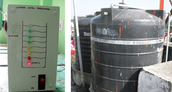
One memorable do-it-yourself design was created for a home supplied by a rooftop water tank. A well pump filled the tank, while gravity provided pressure to the household plumbing. Because the pump had to be operated manually, the homeowner needed a convenient way to monitor the rising water level.
The solution was an LED bar indicator built from basic electronic parts. Several insulated wires extended into the tank at different depths. Each sensing point connected to a transistor, resistors, and an LED. A regulated 5-volt signal was supplied to the sensing circuit.
As the water rose and touched each probe, the conductive water completed a low-current circuit. The corresponding LED illuminated, creating a simple visual scale. One light might indicate a quarter tank, another half full, and the top light would mean it was time to stop the pump.
A buzzer connected to the highest-level circuit provided the most important feature: an audible warning. The owner no longer had to stare at the tank or guess how long filling would take. The system effectively gave the tank a voice, although its vocabulary consisted mainly of “beep,” which is still more useful than silence.
How a Water Tank Level Meter Prevents Overflow
A level meter does not create more tank capacity. Instead, it provides enough information to act before the water reaches the physical overflow point. Depending on the design, the system can perform three related functions.
1. Continuous or Staged Level Indication
A display shows the approximate or exact amount of water in the tank. A basic LED indicator may use four or five stages, while a digital monitor can display water depth, percentage full, or estimated volume.
For a vertical tank with straight sides, the percentage of water depth closely matches the percentage of usable capacity. A tank that is 60% full by height is approximately 60% full by volume. Irregular, conical, or horizontal cylindrical tanks require a more detailed conversion because their cross-sectional area changes with depth.
2. High-Level Alarm
An alarm activates before water reaches the overflow outlet. It may use a buzzer, warning light, mobile notification, or signal sent to a building-control system. The alarm point should leave enough time for the operator to respond and for water already moving through the fill pipe to enter the tank.
For example, a pump delivering 12 gallons per minute can add 60 gallons during a five-minute distraction. A warning that activates only one inch below the overflow may not provide enough reserve capacity, especially in a wide tank.
3. Automatic Pump Shutoff
An automatic controller uses the level signal to operate a relay, contactor, valve, or variable-frequency drive. When the water reaches the upper set point, the controller stops the pump. When the level later falls to a lower set point, it may allow the pump to restart.
The upper and lower thresholds should not be identical. A separation between them, known as hysteresis or differential control, prevents rapid on-and-off cycling as waves move across the water surface. Without that separation, the pump may chatter like an indecisive squirrel at a crosswalk.
Popular Types of Water Tank Level Sensors
No single sensing technology is ideal for every tank. Tank size, water quality, temperature, access, budget, maintenance conditions, and required accuracy all affect the choice.
Conductive Probe Sensors
Conductive probes are similar to those used in the original LED project. When water touches a probe and a reference electrode, a small current flows through the liquid. Electronics detect that change and activate an indicator or switch.
These systems are inexpensive, contain no moving mechanical parts, and can support several detection points. They work well with ordinary conductive water but may not respond reliably to very pure water with extremely low conductivity.
Probe material matters. Constant direct current can contribute to electrode deterioration, mineral deposits, and electrochemical effects. Commercial conductive controllers commonly use small alternating sensing currents and compatible electrode materials to improve service life. Any component touching potable water should also be appropriate for drinking-water contact.
Float Switches
A float switch rises and falls with the water. At a predetermined height, an internal magnet, reed switch, or mechanical linkage changes the electrical contact state.
Floats are affordable, easy to understand, and excellent for simple high- or low-level switching. They are frequently used for pump control and emergency shutdown. However, sediment, tangled cables, turbulent water, or mineral scale can restrict movement.
A float that has not moved in three years may not be “maintenance-free.” It may simply be enjoying retirement without informing the owner.
Ultrasonic Level Sensors
An ultrasonic sensor mounts above the water and sends a sound pulse toward the surface. It measures the return time of the echo and calculates the distance between the sensor and the water. Because the tank height is known, the controller can determine the water level.
Ultrasonic measurement is non-contact, making it attractive for clean-water tanks and applications where submerged hardware is undesirable. It can provide continuous level data and multiple programmable alarm points.
Installation must provide a clear path to the water. Pipes, ladders, tank ribs, angled bottoms, foam, condensation, heavy turbulence, or an incorrectly aimed sensor can cause false echoes. A sensor also has a short blind zone directly below it where accurate measurement may not be possible.
Hydrostatic Pressure Sensors
A hydrostatic sensor measures the pressure created by the column of water above it. Because pressure increases predictably with water depth, the sensor can convert the reading into a level signal.
These sensors can be submerged or connected near the bottom of a tank. They work without a clear acoustic path and are generally unaffected by foam or surface movement. Industrial versions commonly provide a 4–20 mA output that can connect to a controller, remote terminal unit, or supervisory control system.
Accuracy depends on correct installation, calibration, venting, liquid density, and protection from sediment. A pressure port buried under sludge will provide information, but perhaps not the information anyone wanted.
Radar Level Sensors
Radar instruments transmit electromagnetic signals and analyze reflections from the water surface. They offer non-contact continuous measurement and can perform reliably in conditions that challenge some ultrasonic devices.
Radar is common in municipal and industrial installations because it has no float to jam and no probe that must remain clean. Compact radar units are increasingly practical for smaller tanks, although they generally cost more than basic float or conductive systems.
Indicator, Alarm, or Full Automation?
The best system is not automatically the one with the most features. It is the one that matches the consequences of failure.
A visual indicator may be sufficient when the pump switch is nearby and overflow would drain harmlessly outdoors. An audible alarm is better when the operator may leave the area. Automatic shutdown becomes valuable when filling takes a long time, the tank is difficult to access, or an overflow could damage a roof, electrical equipment, inventory, or neighboring property.
Critical systems should not rely on one measurement alone. A continuous sensor can control normal operation, while an independent high-high float switch provides emergency shutdown. That second device should have its own input and, where practical, a separate alarm path.
The physical overflow pipe must remain in place. Electronic controls reduce the probability of overflow, but the overflow outlet protects the tank when a sensor, controller, valve, communication link, or power component fails. It is the mechanical last line of defense, not decorative plumbing.
Designing Reliable Pump-Control Logic
A practical automatic water tank controller usually follows a simple sequence:
- The pump is permitted to start when the water falls below the low-level threshold.
- The pump continues running while the level rises through the normal operating range.
- The pump stops at the full threshold.
- An independent high-high switch stops the pump and triggers an alarm if the normal control fails.
- A low-water safeguard can protect a supply pump from running dry.
Software filtering or a short time delay can prevent splashing from creating nuisance alarms. However, delays should remain short enough to stop filling before the reserve space disappears.
Controllers should also behave safely when a wire breaks or power is lost. In many applications, a high-level safety circuit is designed so that a broken connection produces an alarm or shutdown rather than falsely reporting that everything is fine.
Installation Details That Matter
Choose the Correct Alarm Height
Place the normal full set point below the emergency overflow level. Allow space for pump stopping time, water already inside the pipe, waves, sensor uncertainty, and temporary surges.
Keep Electricity and Water Properly Separated
Immersed sensing circuits should use isolated, current-limited low voltage. A hobby circuit must not switch a large pump motor directly. Use a properly rated relay, motor starter, contactor, or drive installed in accordance with local electrical requirements.
Outdoor equipment needs weather-resistant enclosures, strain relief, protected cable entries, grounding, and suitable overcurrent protection. Work involving line voltage or pump controls should be completed or reviewed by a qualified electrician.
Protect Drinking-Water Quality
Tank openings, probes, cables, vents, and overflow assemblies must be installed without creating a path for insects, dust, runoff, or contaminated liquids to enter. Avoid unapproved sealants, exposed corroding metals, and improvised wiring that makes the lid impossible to close correctly.
A level meter should make stored water easier to manage, not add mysterious flavors.
Calibrate the Display
Record the actual level at empty, full, and several intermediate points. Compare the display with a known reference measurement. For ultrasonic sensors, confirm the programmed tank height and sensor offset. For pressure sensors, verify the zero point and scaling. For staged probes, label each LED according to its real position rather than an optimistic guess.
Maintenance Keeps the Meter Trustworthy
A level system should be tested on a schedule, not only after water appears somewhere it should not. Recommended checks include:
- Activating the high-level alarm manually.
- Confirming that the pump stops at the intended level.
- Inspecting probes for corrosion, scale, and loose connections.
- Checking float switches for free movement.
- Cleaning condensation or debris near non-contact sensors.
- Examining cables, enclosures, seals, relays, and terminals.
- Verifying that the overflow pipe remains open and visible.
- Comparing the electronic reading with a physical reference.
Remote notifications are useful, but they do not replace local testing. A phone application can confidently report “42% full” while a disconnected sensor sits on a workbench. Technology is talented that way.
Practical Benefits Beyond Overflow Prevention
A reliable tank level monitor provides more than a full-tank warning. Historical data can reveal unusually fast consumption, a leaking pipe, a failed check valve, or a pump that is taking longer than normal to refill the tank.
Monitoring can also improve pump scheduling. A household may avoid operating a noisy pump late at night, while a farm or commercial facility can coordinate filling with irrigation demand or off-peak electricity periods.
Low-level alerts prevent unexpected outages and can protect pumps from dry running. A continuous display also helps users understand how everyday activities affect stored-water supplies. Long showers become surprisingly educational when the tank percentage is visible.
Experience-Based Lessons From Real-World Tank Monitoring
The first lesson from installing a water tank level meter is that the display location matters almost as much as the sensor. A perfectly accurate indicator hidden in a utility room is rarely checked. The most useful displays are placed near the pump switch, kitchen entrance, maintenance panel, or another location people naturally pass. A bright full-level light and a buzzer are often more effective than a sophisticated screen requiring three menu taps and a password last seen in 2022.
Simple LED probe systems usually make an excellent first impression. The water rises, another light turns on, and the tank suddenly feels less like a mysterious plastic object on the roof. During early testing, however, probe spacing often needs adjustment. Equal distances between probes do not always represent useful operating stages. Most owners care more about “almost empty,” “enough for today,” and “stop the pump now” than mathematically perfect 20% increments.
Another common experience is discovering that the final few inches fill faster than expected. The tank may have a narrower top, or the inlet pipe may continue draining after the pump stops. Installers who initially position the full sensor very close to the overflow often move it lower after the first wet test. A generous safety margin is much less expensive than repainting a ceiling.
Hard water creates its own personality. Mineral deposits can gradually coat conductive probes or make a mechanical float less enthusiastic about moving. The system may work flawlessly for months and then begin showing a delayed response. Regular inspection usually catches the problem before failure. In tanks with persistent scale, a non-contact sensor may reduce maintenance, provided condensation and tank geometry are handled correctly.
Ultrasonic installations bring a different set of lessons. Mounting the sensor above a pipe, brace, or sloped tank surface may produce convincing but incorrect readings. Moving it only a few inches can transform an unreliable installation into a stable one. A calm patch of open water directly below the sensor is ideal. Software filters help with ripples, but they cannot negotiate with a metal support bar reflecting every sound pulse.
Automatic shutdown also changes user behavior. Once owners trust the system, they stop hovering near the switch. That convenience makes redundancy more important, not less. A separate high-high switch, visible overflow discharge, and manual override provide reassurance when the primary controller fails or maintenance is underway.
Weather exposure deserves attention as well. Sunlight makes inexpensive enclosures brittle, insects explore cable openings, and moisture finds terminals with detective-level determination. Proper glands, drip loops, sealed boxes, and shaded mounting often determine whether a system lasts one rainy season or many years.
The most successful installations are not necessarily the fanciest. They provide a clear reading, an unmistakable warning, safe pump control, and easy testing. Owners understand what each light means, technicians can reach the components, and the overflow pipe remains ready for emergencies. In practice, reliability usually comes from sensible design and routine checks rather than an impressive collection of wireless features.
Conclusion
A water tank level meter prevents overflow by giving users timely, understandable information about the water rising inside a closed container. Even a basic arrangement of probes, transistors, LEDs, and a buzzer can eliminate much of the guesswork associated with manual filling.
More advanced float, ultrasonic, pressure, or radar systems can provide continuous measurement, remote alerts, leak clues, low-level protection, and automatic pump control. The right choice depends on tank geometry, water quality, maintenance conditions, budget, and the consequences of a failure.
Whatever technology is selected, reliable overflow prevention should include a sensible full-level margin, safe electrical installation, regular functional testing, and a physical overflow route. A tank may be silent, but with the right meter attached, it no longer has to keep its water level a secret.
Note: Technical specifications, electrical ratings, potable-water requirements, and installation codes vary by location and application. Pump-control wiring should be designed or reviewed by qualified professionals.