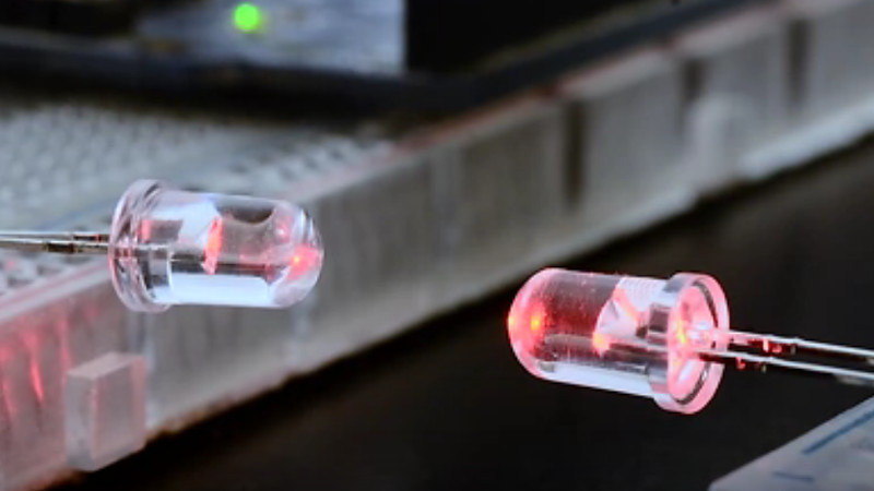

An ordinary light-emitting diode appears to have one straightforward job: turn electricity into light and make a tiny corner of the world glow red, green, blue, or amber. Yet the humble LED has a hidden talent. Under the right electrical conditions, it can reverse roles and detect light as well.
That unusual two-way ability makes optical communication using LEDs alone possible. A pair of inexpensive LEDs, two microcontrollers, a few supporting components, and carefully timed software can form a digital link without a conventional photodiode or radio module. One moment an LED transmits pulses; the next, it listens for light arriving from another device.
This is not a replacement for fiber-optic backbones or high-speed Wi-Fi. It is a clever, low-cost form of visible light communication that is especially useful for experimentation, embedded devices, toys, sensors, identification systems, and situations where radio communication is undesirable. It is also a wonderful reminder that electronic components occasionally have side hustles.
“`
What Is LED-Only Optical Communication?
Optical communication transfers information by changing a light source in a controlled pattern. Traditional systems normally use a light-emitting device at the transmitter and a separate photodiode, phototransistor, or image sensor at the receiver. LED-only communication simplifies that arrangement by using an LED as both the emitter and the detector.
During transmission, a microcontroller drives the LED in its normal forward direction. Digital information is converted into rapid changes in light intensity. During reception, the circuit stops driving the LED and measures the small electrical response produced when incoming light strikes its semiconductor junction.
The result is usually a half-duplex link. Each device takes turns speaking and listening, much like two polite people sharing a walkie-talkie. With precise time multiplexing, an LED can switch between the two roles so quickly that a human observer may perceive it as remaining continuously illuminated.
Visible Light Communication Versus Li-Fi
Visible light communication, commonly abbreviated as VLC, is the broad category covering data transmission through visible light. Li-Fi generally refers to more advanced networking systems that use modulated lighting infrastructure to provide wireless connectivity.
A homemade LED-to-LED link belongs to the VLC family, but calling every blinking breadboard project “Li-Fi” is a little like calling a skateboard a sports car because both have wheels. The fundamental idea is related, while the speed, networking architecture, range, and hardware sophistication may be dramatically different.
How an LED Becomes a Light Detector
An LED is a semiconductor diode built around a junction between materials with different electrical properties. When it is forward biased, electrons and holes recombine in the junction and release energy as photons. The semiconductor material determines the approximate wavelength, and therefore the color, of the emitted light.
The process can also work in the opposite direction. Photons with sufficient energy can enter the junction and create charge carriers. This produces a tiny photocurrent or changes the rate at which charge stored in the junction disappears. Electrically, the LED begins behaving like a small and rather selective photodiode.
“Tiny” is the important word. The detected current is generally much smaller than the current used to illuminate the LED. A microcontroller cannot simply ask, “Is there light?” and expect a strong, cheerful five-volt reply. The signal must be measured through a sensitive analog circuit or an indirect timing technique.
The Junction-Capacitance Timing Method
A popular low-cost method treats the LED junction like a very small capacitor. The microcontroller first charges the junction under controlled conditions. It then changes its input pin to a high-impedance state and measures how long the stored charge takes to fall below a digital threshold.
In darkness, the charge leaks away relatively slowly. When light of a suitable wavelength strikes the LED, the generated photocurrent accelerates the discharge. Software compares the measured time with a threshold and decides whether the incoming optical signal represents a zero, a one, or simply background illumination.
This approach is attractive because it may require no external analog-to-digital converter. It also has limitations: readings depend on the LED, microcontroller input thresholds, parasitic capacitance, ambient light, temperature, wiring, and timing resolution. Breadboard capacitance, in particular, enjoys joining experiments without being invited.
Why LED Color Matters
LEDs are not equally sensitive to every color. A semiconductor junction responds efficiently only to photons energetic enough to excite charge carriers across its bandgap. In practical terms, an LED commonly detects light near its emission color and at somewhat shorter wavelengths, while responding poorly to substantially longer wavelengths.
The colored plastic package can further narrow the response by filtering incoming light. A transparent red LED may respond strongly to certain red, orange, green, or blue sources, depending on its construction, but two visually similar LEDs can behave quite differently. Component selection is therefore an experimental process rather than a beauty contest.
Turning Light Pulses Into Digital Data
Once the LED can transmit and detect light, a communication system still needs rules. Random blinking is expressive, especially around the holidays, but it is not a reliable data protocol.
On-Off Keying
The simplest modulation technique is on-off keying. The transmitter turns the LED on and off according to a timed pattern. Light may represent a binary one and darkness a binary zero, or the protocol may use short and long pulses to make timing easier to recover.
Switching can occur much faster than the human eye can resolve, allowing data to travel without obvious flicker. However, a receiver must distinguish intentional pulses from sunlight, room lighting, display backlights, and other optical noise. A single threshold works on a quiet laboratory bench but may fail spectacularly when someone opens the curtains.
Preambles and Synchronization
A packet normally begins with a recognizable preamble: a known sequence of pulses that helps the receiver detect activity, estimate timing, and adjust its threshold. A synchronization pattern can mark the beginning of the actual message.
Without synchronization, the receiver may sample between pulses and decode a beautiful collection of nonsense. Software-based LED communication systems often devote substantial effort to timing recovery because inexpensive microcontrollers have independent clocks that drift slightly.
Error Detection
Practical packets should include a checksum or cyclic redundancy check. The receiver calculates the value from the incoming data and compares it with the transmitted result. If they disagree, the packet can be discarded or requested again.
Sequence numbers, acknowledgments, retries, addressing, and timeout rules can further improve reliability. These protocol features explain why a robust networking layer may deliver a better experience than a bare loop that flashes eight bits and hopes for the best.
A Basic Two-Device LED Communication System
A minimal demonstration can be built around two Arduino-compatible boards or similar microcontrollers. Each board controls one ordinary LED. The LEDs face one another across a short, unobstructed distance.
In transmit mode, the microcontroller drives its LED through an appropriate current-limiting resistor. In receive mode, it stops forward current, configures the necessary pins for sensing, charges the junction, and measures its discharge response.
The software divides operation into defined time slots. Device A sends while Device B listens. After a guard interval, the roles reverse. The guard interval prevents residual charge, switching delays, or a slow software routine from causing both devices to transmit simultaneously.
A documented maker demonstration combined two LEDs, two Arduino boards, and the PJON networking protocol to exchange data optically. PJON is designed to operate over several physical media and includes addressing, packet handling, acknowledgments, error checking, and retry behavior. That makes it well suited to a weak, noisy optical channel where perfect pulses should never be assumed.
Important Electrical Precautions
Designers should check the LED data sheet before applying reverse voltage. Many indicator LEDs tolerate only a small reverse voltage, and some manufacturers do not recommend reverse operation at all. A sensing circuit should stay comfortably within the component’s rating and limit current in every operating state.
Microcontroller pins must never be connected in a way that allows one output to drive high while another directly drives low without adequate resistance. That arrangement creates a miniature argument between output transistors, and neither side wins.
For better sensitivity and protection, a design can add a transimpedance amplifier, comparator, analog switch, or dedicated input stage. Doing so reduces the purity of an “LEDs alone” demonstration, but it greatly improves a system intended for dependable real-world service.
Benefits of Communicating With Light
Low Component Cost
LEDs are inexpensive, widely available, and already installed in countless products. Reusing an indicator LED as a communication interface may eliminate a separate detector, connector, or radio module.
No Radio-Frequency Congestion
Optical links do not occupy crowded radio channels. They can operate near equipment that is sensitive to radio-frequency interference, provided the optical system itself meets applicable safety and electromagnetic compatibility requirements.
Spatial Confinement
Visible light normally remains within walls and requires a suitable optical path. This physical confinement can reduce accidental reception outside a room. It is not automatic security, however. Light can pass through windows, reflect from surfaces, or be observed by a sufficiently sensitive sensor.
Intentional Alignment
Directionality can be useful when two devices should communicate only after being placed face-to-face. A service tool might exchange configuration data through a status LED, or two toys could recognize one another when their “eyes” are aligned.
Communication and Indication in One Part
Time multiplexing allows the same LED to serve as a status lamp, transmitter, and receiver. This can simplify a product enclosure and create interfaces that remain nearly invisible until needed.
Limitations of LED-to-LED Communication
An ordinary LED is not optimized as a detector. Its sensitive area may be small, its photocurrent weak, and its field of view limited by the package lens. A purpose-built photodiode usually provides better sensitivity, predictable spectral data, faster response, and easier analog design.
Line-of-sight alignment is another major constraint. Distance increases optical loss rapidly as emitted light spreads. Lenses, reflectors, light pipes, or optical fiber can improve coupling, but each addition changes the cost and mechanical complexity.
Ambient light can shift the baseline or saturate a sensitive receiver. Sunlight is particularly challenging because it is intense and covers a broad spectrum. Fluorescent lamps, dimmed LED bulbs, displays, and automotive lighting may introduce periodic interference.
LED-only links are also generally low-rate compared with optimized VLC systems. Research platforms have shown room-scale LED-to-LED networking with inexpensive hardware, but the most practical applications emphasize simplicity and low power rather than broadband performance.
Ways to Improve Reliability
Start with mechanical design. Place both LEDs in dark tubes or behind apertures to reduce off-axis light. Keep their optical axes aligned and choose packages with suitable viewing angles. A narrow lens may increase distance but make alignment more demanding.
Use adaptive thresholds rather than relying on one fixed value. The receiver can measure the background level before each packet and look for changes relative to that baseline. High-pass filtering can suppress slow changes caused by daylight or shadows.
Modulation at a selected carrier frequency can distinguish transmitted data from steady ambient light. The receiver then searches for energy near that frequency instead of treating every brightness change as meaningful.
Packet-level techniques are equally important. Add preambles, balanced data coding, checksums, acknowledgments, retry limits, and sequence numbers. Keep packets short when the error rate is high, since retransmitting a small packet is less painful than repeating a miniature novel.
Where LED-Only Optical Links Can Be Useful
The technology is appealing for educational demonstrations because it combines semiconductor physics, embedded programming, networking, optics, and signal processing in one approachable project.
It can also support low-cost toys, interactive exhibits, wearable accessories, device pairing, identification tags, isolated control panels, short-range sensor nodes, and configuration interfaces. An appliance could receive setup information through its indicator lamp, avoiding an exposed connector.
Optical links may be useful across transparent barriers where electrical isolation is required. They can also communicate through plastic light guides or short pieces of optical fiber. In such systems, however, engineers should compare the LED-only approach with conventional optocouplers, infrared transceivers, and fiber-optic modules before choosing novelty over reliability.
Practical Experiences and Lessons From LED Communication Projects
The first experience many builders have with an LED receiver is mild disbelief. Connecting a voltmeter to an illuminated LED may reveal a small voltage, but turning that effect into clean digital data is less immediate. The signal can disappear when the LED is moved a few inches, rotated slightly, or exposed to a different lamp. This is normal. The experiment is demonstrating both photodetection and the unforgiving geometry of free-space optics.
Test LED Pairs Before Designing the Full Circuit
LEDs that look identical may produce very different sensing results. A productive workflow begins by testing several colors, package styles, and manufacturers. Clear-lens LEDs often provide better optical access, while heavily tinted packages may reject unwanted wavelengths or may reject the desired transmitter along with them.
Measuring charge-discharge timing under darkness, room light, and direct illumination quickly reveals which combinations provide the largest separation. Selecting the best pair early can save hours of software tuning later.
Alignment Matters More Than Expected
A link that works reliably at ten inches on a bench may fail after the boards are placed in enclosures. The LED lens, mounting angle, enclosure opening, and nearby reflective surfaces all affect received power. Builders often improve performance dramatically by adding simple black tubes made from heat-shrink tubing, drinking straws, or 3D-printed holders.
Those tubes block side illumination and help maintain alignment. They may not win an industrial design award, but neither does a project that stops communicating whenever someone turns on a desk lamp.
Ambient Light Is a Moving Target
Testing only in a dim room creates false confidence. A reliable prototype should be challenged under sunlight, fluorescent lighting, dimmable LED bulbs, computer monitors, and moving shadows. Each environment produces a different background signal.
Sampling the background immediately before a packet is often more useful than calibrating once at startup. Averaging several samples reduces noise, while a preamble allows the receiver to estimate the current pulse amplitude.
Timing Bugs Often Look Like Optical Problems
When packets fail, the instinct is to blame weak light. In many projects, the true cause is clock drift, interrupt latency, inconsistent loop timing, or transmitter and receiver state machines that disagree about when a bit begins.
Logging measured pulse widths and state transitions is more informative than repeatedly moving the LEDs closer together. A logic analyzer can inspect the electrical drive signal, while a second photodetector or oscilloscope can reveal what the optical waveform actually looks like.
Build the Simplest Link First
Begin with one-way transmission of a repeating pattern. Add packet framing only after individual bits are detected consistently. Next introduce checksums, acknowledgments, and bidirectional time slots. Trying to debug sensing, modulation, synchronization, and a complex network protocol simultaneously is an excellent method for developing strong opinions about breadboards.
The most important lesson is that LED-only communication works because hardware and software cooperate. The LED provides a weak but usable physical channel. Mechanical alignment increases received energy. Signal processing separates data from background light. The protocol detects mistakes and tries again. None of these layers is especially powerful alone, but together they turn two inexpensive glowing components into a surprisingly capable conversation.
Conclusion
Optical communication using LEDs alone transforms a familiar indicator into a bidirectional optical transceiver. By alternating between forward-driven emission and carefully measured photodetection, two microcontroller-based devices can exchange digital packets through visible light.
The approach is inexpensive, educational, spatially confined, and free from radio-spectrum congestion. Its weaknesses include short range, modest sensitivity, alignment requirements, ambient-light interference, and lower throughput than systems built with dedicated optical receivers.
Even with those limitations, LED-to-LED communication is more than a laboratory curiosity. It demonstrates how thoughtful timing, packet design, and signal processing can uncover capabilities hidden inside ordinary components. The next time an LED blinks on a circuit board, remember: it may not be showing off. It may be trying to say something.