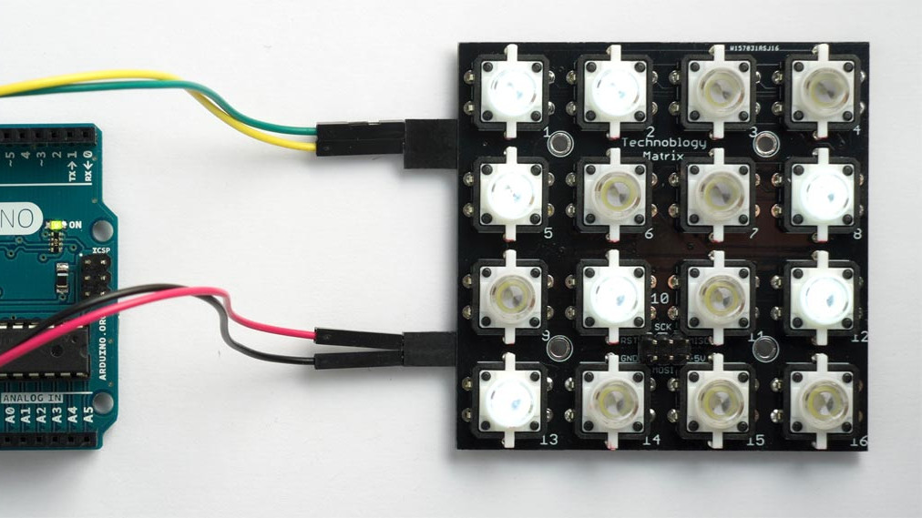

A DIY button matrix is one of those projects that looks simple until you start counting wires. Sixteen buttons? Fine. Sixteen lights? Still fine. Sixteen illuminated buttons that can be read clearly, display patterns, report multiple presses, and communicate over I2C using only a couple of host pins? Now we are in “tiny control panel with a surprisingly big personality” territory.
The idea behind a DIY illuminated button matrix is beautifully practical: arrange pushbuttons in a grid, add LEDs so each button can glow, and let a small microcontroller handle the busy work. Instead of forcing your main Arduino, Raspberry Pi, ESP32, or other controller to scan every switch and refresh every LED, the button board becomes its own smart I2C device. The main system simply asks, “Which buttons are pressed?” or says, “Please light these buttons,” and the matrix board does the rest without complaining, sighing, or stealing every GPIO pin in the room.
For makers building games, MIDI controllers, puzzle boxes, interactive art, control panels, educational devices, or custom human-machine interfaces, this design hits a sweet spot. It is compact, scalable, affordable, and very hackable. Better yet, it teaches several core electronics lessons at once: matrix wiring, LED multiplexing, I2C communication, debounce handling, interrupts, pull-up resistors, firmware organization, and printed circuit board design. In other words, it is a small project with a large syllabus.
What Is a DIY Button Matrix?
A button matrix is a grid of switches arranged in rows and columns. Instead of wiring every button separately to a controller pin, you connect switches at row-column intersections. A 4×4 matrix gives you 16 buttons with far fewer pins than 16 independent inputs would normally require. This is why keypads, keyboards, calculators, remote controls, and arcade-style input panels often use some form of matrix scanning.
In a basic matrix, the controller energizes or reads one row or column at a time and checks which intersections are active. Pressing a button connects a row to a column, allowing the firmware to identify the button position. It is the electronics equivalent of calling roll in a classroom: “Row two, column three, are you here?” If the answer is yes, the firmware records that button as pressed.
An illuminated button matrix adds a second layer: LEDs. Each button is not just an input but also a visual output. That means the board can guide a user, show status, display game states, flash alerts, or create animations. A glowing button can say “press me,” “you already pressed me,” “wrong choice,” “good job,” or “I am the dramatic one.”
Why I2C Makes the Button Matrix Smarter
I2C, short for Inter-Integrated Circuit, is a two-wire communication bus commonly used to connect chips, sensors, displays, GPIO expanders, and small peripherals. It typically uses two signal lines: SDA for data and SCL for clock. Multiple devices can share the same bus as long as each device has a unique address.
For a DIY button matrix, I2C solves a familiar maker problem: limited pins. A microcontroller board may have plenty of processing power but not enough convenient GPIO for 16 switches, 16 LEDs, and everything else in the project. By putting a small controller or I/O device on the button board, the entire panel can communicate through I2C. The host only needs power, ground, SDA, and SCL. Add an interrupt line, and the host can be notified when something changes instead of constantly polling like an anxious doorbell camera.
The Big Advantages of an I2C Button Matrix
- Fewer host pins: The main controller uses only two I2C pins, plus optional interrupt.
- Cleaner wiring: One cable can replace a spaghetti bowl of individual switch and LED wires.
- Reusable design: The same board can work with Arduino, ESP32, Raspberry Pi, RP2040, or other I2C-capable systems.
- Independent input and output: Button states can be read while LED states are controlled separately.
- Expandable panels: Multiple boards can be tiled or chained if address planning is handled correctly.
- Better responsiveness: Interrupts let the host react quickly when a button changes state.
The Core Hardware: Buttons, LEDs, Microcontroller, and PCB
A practical 4×4 illuminated button matrix usually includes sixteen momentary pushbuttons, sixteen LEDs or integrated illuminated buttons, current-limiting resistors, a microcontroller or I/O expander, pull-up resistors, and a printed circuit board. The PCB is not just a luxury here. Once buttons and LEDs multiply, a breadboard becomes less “prototype station” and more “haunted telephone exchange.”
Many successful DIY versions use a small microcontroller such as an ATtiny-class chip to manage both the inputs and LEDs. The host system sees the board as an I2C peripheral. Internally, the onboard controller reads the switches, debounces the input, refreshes the LEDs, and responds to I2C commands. That approach makes the board feel like a polished module rather than a pile of parts begging for cable management.
Another route is to use a dedicated I2C GPIO expander or keypad controller. Chips such as the MCP23017 provide 16 bits of I/O expansion over I2C, while keypad scanner chips such as the TCA8418 can manage larger keypad arrays and provide event queues, debounce support, and interrupt features. A dedicated keypad controller can be very convenient, especially when the project needs many switches but not much custom LED behavior. A microcontroller-based design gives more flexibility for animation, custom protocols, and combined button-light logic.
How the 4×4 Illuminated Matrix Works
A 4×4 illuminated button matrix can be understood as two systems sharing the same physical layout: the switch input system and the LED output system.
Reading the Buttons
Each pushbutton must be read reliably. In some designs, each button connects to its own microcontroller input. This uses more pins on the onboard controller, but it has an excellent advantage: multiple simultaneous button presses can be detected clearly without ghosting. Ghosting is the classic matrix-keypad problem where pressing certain combinations makes the controller think an extra button is pressed. It is like the electronics version of hearing one cat meow and blaming three cats.
If a design uses traditional row-column scanning, diodes may be added to prevent ghosting when multiple buttons are pressed. For game controllers, music gear, and puzzle interfaces where users may mash several buttons at once, unambiguous multi-press detection is important. Nobody wants a game to fail because the keypad invented a phantom button press at the worst possible time.
Lighting the LEDs
The LED side is often handled through multiplexing. Instead of powering every LED continuously with its own dedicated driver pin, the firmware lights one row or group at a time very quickly. Human eyes blend the rapid refresh into steady illumination. This reduces the number of pins and components needed while still allowing each button to appear independently controlled.
For example, the firmware may hold a 16-bit value in memory, where each bit represents one light. A value of 1 means the LED should be on, and a value of 0 means it should be off. During refresh, the firmware selects a row, applies the correct LED pattern for that row, then moves to the next row. If this happens fast enough, the whole panel appears stable.
Talking Over I2C
The I2C protocol can be simple. The host writes two bytes to set the LED pattern and reads two bytes to get the button state. Sixteen buttons fit neatly into 16 bits, and sixteen LEDs also fit into 16 bits. Button one can be bit zero, button two can be bit one, and so on. This is compact, fast, and friendly to small microcontrollers.
A basic host interaction might look like this conceptually:
That could mean a row of LEDs is lit, while buttons one and three are currently pressed. The actual byte order and address depend on the firmware, but the principle is wonderfully direct.
Interrupts: The Button Board Raises Its Hand
An interrupt line is optional but extremely useful. Without an interrupt, the host controller must ask the button matrix for its state again and again. That works, but it wastes time and bus traffic. With an interrupt, the matrix pulls a signal low or high when a button state changes. The host then knows it should read the current button state.
This is especially helpful in battery-powered projects or systems where the main controller is busy doing other things, such as playing audio, driving a display, managing wireless communication, or pretending it is not overwhelmed. Interrupt-driven input feels more responsive and efficient.
Debouncing: Because Buttons Are Tiny Liars
Mechanical buttons do not usually transition from open to closed in one perfect instant. When pressed, the contacts may bounce electrically for a few milliseconds. To a fast microcontroller, one press can look like several rapid presses. This is called switch bounce, and it is the reason your firmware needs debounce logic.
Debouncing can be done in hardware with capacitors and resistors, but software debounce is common and flexible. The firmware may read the button state repeatedly and accept it only after it remains stable for a short period. This prevents false triggers and makes the button matrix feel professional. Without debounce, a simple game can become a chaos simulator with LEDs.
Choosing Between a Microcontroller and an I2C Expander
There is no single correct architecture for every DIY button matrix. The right choice depends on your goals.
Use a Microcontroller When You Want Flexibility
A small onboard microcontroller is ideal when you want custom LED animation, special button behavior, advanced debounce routines, sleep modes, or a custom I2C command set. It can act like a tiny co-processor dedicated to the panel. This approach is especially attractive for interactive art, games, musical instruments, and modular control surfaces.
Use an I/O Expander When You Want Simplicity
An I2C GPIO expander is a good choice when you simply need more inputs or outputs. The MCP23017, for example, is widely used because it offers 16 I/O lines and communicates over I2C. It can read buttons, drive simple outputs, and reduce the pin burden on the host controller. However, the host may still need to handle scanning, debounce, or LED refresh depending on the circuit.
Use a Keypad Scanner When You Want Button Handling Built In
A keypad controller such as the TCA8418 is designed specifically for matrix input. It can support large key arrays, store key events, debounce inputs, and trigger interrupts. That makes it excellent for keypads and compact control panels. If your project is mostly about reading buttons, a keypad scanner can save a lot of firmware effort. If your project needs rich LED control inside each button, a microcontroller-based board may still be more flexible.
Design Tips for a Reliable DIY Button Matrix
Good button matrix design is not only about making it work once on the bench. It is about making it work every time after being moved, bumped, installed in an enclosure, and operated by someone who presses buttons with the enthusiasm of a game-show contestant.
Plan the Power Budget
LEDs consume current, and sixteen illuminated buttons can add up quickly. Multiplexing reduces average current, but brightness expectations still matter. Choose resistor values carefully, check the current rating of the microcontroller pins, and avoid asking tiny I/O pins to behave like power drivers. If the LEDs need more current than the chip can safely provide, use transistor drivers or LED driver ICs.
Use Pull-Up Resistors Correctly
I2C lines require pull-up resistors because SDA and SCL are commonly open-drain or open-collector style signals. Many breakout boards already include pull-ups, but stacking several I2C boards can make the effective resistance too low. Long wires can also add capacitance and distort signals. For short maker projects, common values such as 4.7 kΩ are often used, but the best value depends on voltage, bus speed, cable length, and total bus capacitance.
Keep the I2C Wiring Sensible
I2C is happiest on short board-level connections. It can work over cables in many hobby projects, but it is not magic. Keep SDA and SCL reasonably short, share a solid ground, avoid running the bus next to noisy motors or high-current LED strips, and slow the bus down if reliability becomes questionable. When in doubt, use an oscilloscope or logic analyzer. The logic analyzer, in particular, is the therapist your I2C bus never knew it needed.
Label the Board Clearly
If you are designing a PCB, label power, ground, SDA, SCL, interrupt, address jumpers, and orientation marks. Future-you will appreciate it. Future-you is tired, probably holding the board upside down, and wondering why nothing works.
Example Projects That Benefit From an I2C Illuminated Button Matrix
A DIY button matrix that lights up and speaks I2C is more than a neat electronics exercise. It is a reusable interface module. Here are several practical uses:
- Puzzle boxes: Light clues, detect sequences, and trigger secret compartments.
- DIY MIDI controllers: Use illuminated pads for samples, loops, banks, or transport controls.
- Mini arcade games: Build memory games, Lights Out variants, reaction games, or pattern puzzles.
- Home automation panels: Show device status and accept quick controls for lights, scenes, or sensors.
- Robotics control panels: Provide mode selection, emergency states, and feedback indicators.
- Educational kits: Teach binary, I2C, embedded programming, matrix scanning, and input handling.
- Interactive exhibits: Create durable, tactile interfaces for museums, classrooms, or maker fairs.
Firmware Strategy: Keep It Small, Fast, and Predictable
The firmware for a smart button matrix should be boring in the best possible way. Boring firmware is reliable firmware. It should initialize the I/O pins, set up I2C communication, configure interrupts or polling, refresh the LED display at a steady rate, debounce button input, and respond to host commands.
A clean design separates responsibilities. One function reads keys. Another updates lights. Another handles I2C writes. Another handles I2C reads. Timer interrupts can manage LED multiplexing so the display refresh does not depend on the main loop. Pin-change interrupts can flag button changes. The main loop may even be nearly empty if the work happens through interrupts and I2C callbacks.
Still, simplicity matters. Interrupts are powerful, but too many interrupt routines can make debugging harder. Polling can be easier to reason about and may be fast enough for many button panels. The best design balances responsiveness with maintainability. If the panel is dedicated only to buttons and LEDs, scanning a few hundred times per second is usually not difficult.
Common Mistakes to Avoid
Forgetting Current-Limiting Resistors
LEDs need current control. Skipping resistors may produce one brief heroic flash followed by silence, sadness, and the smell of poor decisions.
Ignoring Button Ghosting
If your design uses row-column scanning and allows multiple simultaneous presses, add diodes or use a scanning method that prevents ambiguity. This is especially important for games and musical controls.
Mixing 3.3V and 5V Without Thinking
Many modern microcontrollers use 3.3V logic. Some older Arduino boards use 5V. I2C voltage levels must be compatible. Use level shifting when required, and check whether breakout boards already include it.
Using the Same I2C Address Twice
Two devices with the same I2C address on one bus will cause trouble unless the address can be changed or an I2C multiplexer is used. Plan addresses before tiling multiple button panels.
Putting Too Much Trust in Breadboards
Breadboards are great for experiments, but a 4×4 illuminated button matrix has enough connections to justify a PCB or at least a carefully soldered prototype board. Loose jumper wires are tiny chaos antennas.
Builder Experience: What It Feels Like to Make One
Building a DIY button matrix that lights up and speaks I2C is satisfying because the progress is visible at every stage. The first win is mechanical: sixteen buttons lined up in a clean grid. Even before the board works, it looks like something important. It has the unmistakable vibe of a spaceship control panel, even if it is currently connected to a USB cable and sitting next to a coffee mug.
The second win comes when the first LED lights. At that moment, the project changes from “collection of parts” to “device.” A single glowing button has a strange emotional power. It invites interaction. It says, “Yes, I am alive, and yes, you should absolutely press me.” Then you light a row, then a pattern, then all sixteen, and suddenly you are making animations instead of finishing the firmware. This is normal. It is also why projects take longer than expected.
The first real challenge is usually mapping. Button one may not be where the firmware thinks button one is. LED seven may be wired like LED ten. Rows may be inverted. Bits may appear backward. This is where a simple test sketch becomes essential. Light each LED in order. Print each button press in order. Do not try to debug the full application until the hardware map is correct. Otherwise, you will spend an evening chasing a “software bug” that is actually one swapped column and a bruised ego.
Debounce testing is another memorable step. A button may look perfect to your finger but noisy to the microcontroller. Without debounce, one press may register as three or four. The first time this happens in a game prototype, it feels like the button is cheating. Add a stable-read routine or a small debounce delay, and the panel immediately feels more polished. This is one of those upgrades users never notice when it is done right, but they absolutely notice when it is missing.
I2C testing can be both delightful and mildly humbling. When it works, it feels almost too easy: write two bytes, lights change; read two bytes, button states arrive. When it fails, check the basics first. Is ground shared? Are SDA and SCL swapped? Is the address correct? Are pull-ups present? Is the host using the right voltage? Most I2C problems are not mysterious. They are ordinary wiring problems wearing a small digital mustache.
Enclosure planning is also part of the experience. Illuminated buttons deserve a clean front panel. Laser-cut acrylic, 3D-printed bezels, wood panels, aluminum plates, or even repurposed plastic boxes can work. The important detail is spacing. Fingers need room. Labels need visibility. If the buttons are too close together, users will press two at once and blame the device, not their enthusiastic thumbs.
Once the project is finished, the best part is how reusable it becomes. The same I2C button matrix can be a game controller today, a MIDI pad tomorrow, and a smart home scene selector next weekend. That modularity is the real reward. You are not just building a keypad; you are building a small, glowing language for your projects.
Conclusion
A DIY button matrix that lights up and speaks I2C is a compact lesson in smart interface design. It reduces wiring, saves host GPIO pins, improves modularity, and gives your project a tactile interface that feels far more polished than plain switches. Whether built around an ATtiny-style microcontroller, a GPIO expander, or a dedicated keypad scanner, the concept is the same: let a small board handle the button-and-light workload while the main controller focuses on the larger application.
The best versions are thoughtfully designed. They debounce inputs, handle multiple button presses clearly, refresh LEDs smoothly, respect I2C electrical limits, and provide an interrupt signal when the host needs quick updates. Add a clean PCB and a tidy enclosure, and the result can look like a professional control module instead of a weekend wiring experiment that escaped containment.
For makers, the charm is obvious. A 4×4 illuminated I2C button matrix is useful, educational, affordable, and endlessly reusable. It can become a game board, a music controller, a robot panel, an art interface, or the glowing command center your desk secretly deserves. And honestly, any project that combines buttons, lights, and a tiny chip politely speaking I2C has already earned its place in the workshop.
Note: This article is synthesized from real-world maker practices, documented illuminated button matrix projects, microcontroller design patterns, I2C communication principles, keypad scanner behavior, and commonly used GPIO expansion approaches. Always verify pinouts, voltage levels, current limits, and component datasheets before building or publishing a final circuit.