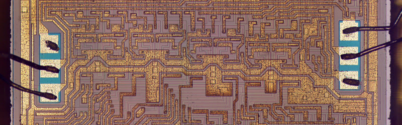

The 74181 ALU is one of those chips that looks innocent until you open the datasheet and realize it has more personality than some modern processors. Officially, it is a 4-bit arithmetic logic unit and function generator from the classic 7400 TTL family. Unofficially, it is a tiny silicon gymnasium where addition, subtraction, comparison, Boolean logic, carry lookahead, and vintage computer history all do push-ups together.
Before single-chip microprocessors became the norm, computer designers built CPUs from many smaller logic chips. The arithmetic logic unit, or ALU, was the part responsible for doing math and logic: adding numbers, subtracting values, comparing operands, and performing operations such as AND, OR, XOR, and NOT. The 74181 compressed a complete 4-bit ALU into a single package, making it a landmark part in minicomputers, educational CPU projects, and bit-slice computer design.
This article explains how the 74181 works, why its function table looks strange at first glance, how its carry system makes it fast, and why the chip still matters to anyone learning digital logic today.
What Is the 74181 ALU?
The 74181 is a 4-bit arithmetic logic unit. That means it takes two 4-bit input words, usually called A and B, and produces a 4-bit result called F. It can perform logic operations, arithmetic operations, and comparison-related functions depending on the control signals applied to its pins.
The chip belongs to the TTL logic era. TTL stands for transistor-transistor logic, a technology built around bipolar transistors. Modern CPUs contain billions of MOS transistors and can run at gigahertz speeds, but the 74181 comes from a world where reducing a processor from several boards to fewer boards was a major victory. It was not just a chip; it was a space-saving miracle with legs.
Main Signals on the 74181
The 74181 has several important inputs and outputs:
- A0–A3: Four bits of the first operand.
- B0–B3: Four bits of the second operand.
- S0–S3: Four function-select inputs that choose the operation.
- M: Mode control input. It selects logic mode or arithmetic mode.
- Cn: Carry input used during arithmetic operations.
- F0–F3: Four result outputs.
- Cn+4: Carry output from the 4-bit slice.
- P and G: Propagate and generate outputs for carry lookahead.
- A=B: Equality comparison output.
The “4-bit slice” idea is central. One 74181 handles four bits. If a designer wants an 8-bit ALU, two chips can be connected. For 16 bits, four chips are used. For wider machines, designers repeat the pattern. This is called bit-slice architecture, and it was a practical way to build processors before everything moved into one giant integrated circuit.
Logic Mode: The 16 Boolean Functions
The easiest way to understand the 74181 is to begin with logic mode. When the mode input selects logic operation, the ALU disables arithmetic carry behavior and acts like a Boolean function generator.
With two one-bit inputs, A and B, there are exactly 16 possible Boolean functions. That number comes from the truth table. A and B can form four input combinations: 00, 01, 10, and 11. For each row, the output can be either 0 or 1. Since there are four rows and two possible outputs for each row, the total number of functions is 24, or 16.
The 74181 implements all 16 of them. That includes familiar operations such as:
- A AND B
- A OR B
- A XOR B
- NOT A
- NOT B
- NAND
- NOR
- Equivalence, sometimes described as XNOR
It also includes less glamorous functions, such as always-zero, always-one, A AND NOT B, and other combinations that are mathematically valid even if they do not usually get invited to dinner parties.
Example: Using the 74181 for XOR
Suppose A is 1010 and B is 1100. A XOR B compares each bit and returns 1 where the bits are different:
A: 1010
B: 1100
F: 0110
In logic mode, the 74181 can generate this result directly by setting the select lines to the XOR function. No addition happens, no carry is needed, and the chip behaves like a flexible bundle of logic gates.
Arithmetic Mode: Where the Chip Gets Interesting
Arithmetic mode is where the 74181 earns its reputation for being both brilliant and slightly weird. At first, the arithmetic function table seems to contain normal operations such as addition, subtraction, increment, decrement, and comparison. Then it also shows odd-looking operations that resemble “A plus A AND B” or “A plus A OR NOT B.” That is the moment many beginners stare at the datasheet and wonder whether the chip had too much coffee.
The trick is that the arithmetic side is not a random list of hand-picked operations. A good way to understand it is this: the 74181 forms arithmetic functions by adding A to a selected Boolean function of A and B, plus the carry input. In simplified form:
F = A + f(A, B) + carry
The function f(A, B) is chosen by the same four select lines. Because there are 16 possible Boolean functions of A and B, the chip can produce 16 arithmetic behaviors. Some are everyday operations. Some are strange but logical consequences of the internal design.
How Addition Works
For addition, the selected internal function behaves like B. The ALU then computes:
F = A + B + carry
If the carry input represents zero, the result is simple addition. If the carry input represents one, the result is addition with carry. This is exactly what a multi-word CPU needs when adding numbers wider than four bits. The lower 4-bit slice can pass a carry into the next slice, and the upper slice continues the operation.
Example: Adding Two 4-Bit Numbers
Let A = 0101, which is decimal 5, and B = 0011, which is decimal 3. In addition mode with no carry-in:
0101 + 0011 = 1000
The output F becomes 1000, or decimal 8. If a carry-in is active, the chip would add one more, producing 1001, or decimal 9.
How Subtraction Works
Subtraction in binary hardware is usually performed with two’s complement arithmetic. Instead of building a separate subtractor, the circuit complements the subtrahend and adds one. In other words:
A – B = A + NOT B + 1
The 74181 uses this principle. By selecting the correct function and carry condition, it can compute subtraction, subtraction with borrow, comparison, and related operations. This is why the carry input matters so much. It is not decorative. It is the tiny doorman deciding whether the arithmetic party gets one extra bit.
The Role of the Mode Input M
The M input is the main switch between logic and arithmetic behavior. In logic mode, the internal carry chain is disabled, so the chip produces pure Boolean functions. In arithmetic mode, the carry chain is enabled, so operations can include addition, subtraction, incrementing, decrementing, and carry propagation.
This is one reason the 74181 is more than just a collection of gates. It is a configurable machine. The same A and B inputs can produce entirely different results depending on M and the four select lines. A modern analogy would be a kitchen appliance that can chop vegetables, make espresso, calculate taxes, and judge your soldering technique. The 74181 is not quite that versatile, but for TTL logic, it gets close.
Why the Function Table Looks So Strange
Many people meet the 74181 through its function table, and the first reaction is usually confusion. Some rows look obvious. Others look like algebraic soup. The reason is that the chip was designed around efficient internal logic, not around making the datasheet look friendly on a classroom projector.
The logic functions are all possible Boolean functions of A and B. The arithmetic functions are related to adding A to one of those Boolean functions. Once that pattern is visible, the weirdness starts to fade. The chip is not random. It is systematic. It simply exposes functions that fall naturally out of the hardware, even if a programmer would rarely choose some of them directly.
This is an important lesson in digital design: hardware often reflects implementation efficiency. A function may exist not because it is popular, but because the circuit can provide it cheaply once the required gates are already there.
Carry Lookahead: The Speed Secret
Binary addition has a classic speed problem. In a simple ripple-carry adder, each bit must wait for the carry from the previous bit. If bit 0 produces a carry, bit 1 needs it. If bit 1 produces a carry, bit 2 needs it. The carry ripples across the word like a nervous intern passing a message down a hallway.
That works, but it is slow for wider words. The 74181 improves performance by using carry lookahead. Instead of waiting for carries to ripple one by one, the chip generates internal signals that predict whether each bit position will generate a carry or propagate a carry.
Generate and Propagate
The idea can be summarized like this:
- Generate: A bit position creates a carry regardless of the incoming carry.
- Propagate: A bit position passes an incoming carry to the next stage.
By combining generate and propagate information, the ALU can determine carry values faster than a ripple-carry adder. The 74181 provides P and G outputs so multiple chips can be connected efficiently. When paired with a carry lookahead generator such as the 74182, designers can build wider ALUs with much less carry delay.
Building Wider ALUs
One 74181 gives a 4-bit ALU. Two chips can form an 8-bit ALU. Four chips can form a 16-bit ALU. Each slice handles its own four bits, while carry signals connect the slices. For small designs, designers may simply feed the carry output of one chip into the carry input of the next. For faster designs, external carry lookahead logic uses the P and G outputs to anticipate carries across several slices.
This modular structure made the 74181 attractive in minicomputers and custom processors. It allowed engineers to build the word size they needed without designing a full ALU from scratch.
The A=B Output and Comparison
The 74181 can also assist with comparison. The A=B output indicates equality under the proper operating conditions. Internally, the chip can decode whether the function outputs show that the two operands match. In multi-chip systems, equality outputs can be combined to compare wider values.
Magnitude comparison is also possible by interpreting the carry output during subtraction-like operations. For example, if a system computes A minus B, the resulting carry or borrow behavior can help determine whether A is greater than, equal to, or less than B. This is a classic hardware trick: do subtraction, then examine the flags.
Active-Low Signals: The Part That Trips People
One of the most confusing parts of the 74181 is signal polarity. Many pins in the datasheet are shown with bars over their names, meaning they are active-low. An active-low signal is considered asserted when it is at logic 0 rather than logic 1.
This matters because the same physical chip can be described using active-low or active-high interpretations. The function tables may look different depending on which convention is used. Beginners often think they selected the wrong operation when the real issue is that they are reading the wrong polarity table.
The practical advice is simple: pick one interpretation, label your signals clearly, and follow the matching function table. When breadboarding the 74181, always check whether your LEDs, switches, and pull-up or pull-down resistors match the signal polarity. Otherwise, the chip may be doing exactly what you asked while your test setup tells a dramatic lie.
Historical Importance of the 74181
The 74181 arrived at a pivotal moment in computing history. Before highly integrated microprocessors, CPUs were assembled from many chips across one or more circuit boards. By placing a 4-bit ALU on a single TTL chip, the 74181 reduced chip count and simplified processor design.
It appeared in or influenced many bit-slice and minicomputer designs, and it remains a favorite teaching device because it makes CPU architecture visible. Unlike a modern processor, where the ALU is buried inside layers of silicon abstraction, the 74181 puts the concept on a 24-pin package that students can wire, probe, and occasionally blame for mistakes caused by their own jumper wires.
Specific Example: Designing an 8-Bit ALU With Two 74181 Chips
Imagine building an 8-bit CPU. You can divide the byte into two nibbles. The lower 74181 handles bits 0 through 3, and the upper 74181 handles bits 4 through 7. Both chips receive the same function-select lines and the same mode signal, so they perform the same operation at the same time.
For addition, the lower chip processes the lower nibble. If it produces a carry, that carry must affect the upper nibble. In the simplest design, the carry output of the lower chip connects to the carry input of the upper chip. This creates a ripple between the two slices. For a faster design, the propagate and generate outputs from both chips can be sent to carry lookahead logic, which calculates carries more quickly.
For example, adding 1111 1111 and 0000 0001 should produce 0000 0000 with a carry out. The lower nibble adds 1111 and 0001, producing 0000 and a carry. The upper nibble adds 1111 and 0000 plus that carry, producing 0000 and a final carry. That is how two 4-bit slices behave like one 8-bit ALU.
Why the 74181 Still Matters
The 74181 is no longer a mainstream commercial computing component, but it remains useful for learning. It teaches several ideas at once: Boolean functions, arithmetic circuits, two’s complement subtraction, carry lookahead, active-low logic, comparison flags, and modular CPU design.
Software developers can also benefit from understanding it. The flags inside a CPU, such as carry, zero, sign, and overflow, are not magical symbols invented by assembly-language manuals. They come from real hardware behavior. The 74181 helps connect those flags to gates, carries, and result bits.
For electronics hobbyists, the chip is a doorway into homebrew computing. For computer architecture students, it is a compact case study. For retrocomputing fans, it is a reminder that older hardware solved hard problems with elegance, discipline, and just enough weirdness to keep the datasheet spicy.
Common Mistakes When Learning the 74181
Reading the Wrong Function Table
The 74181 datasheet may present active-low and active-high interpretations. Mixing them up leads to confusion. Always confirm which table matches your wiring and notation.
Forgetting the Carry Input
Arithmetic operations depend on the carry input. The same select-line setting can produce related but different results depending on whether carry is asserted.
Expecting Multiplication or Division
The 74181 does not directly multiply or divide. Those operations can be built from repeated addition, subtraction, and shifting, but they are not single-step functions of the chip.
Ignoring Active-Low Outputs
Some outputs and control interpretations are active-low. If an LED appears backward, the chip may not be broken. Your indicator circuit may simply be judging upside down.
Experience Notes: What Working With the 74181 Teaches You
Working with the 74181 is a very different experience from writing a line of code and watching a simulator politely obey. The first lesson is humility. On paper, the chip seems straightforward: connect A, connect B, choose a function, read F. On a breadboard, however, every loose jumper wire becomes a tiny philosopher asking, “Are you sure?”
The most useful experience is to start in logic mode. Set up switches for A and B, connect LEDs to the output, and test simple functions such as AND, OR, and XOR. This gives immediate feedback and helps build confidence. XOR is especially satisfying because the pattern is easy to verify. If the input bits differ, the output lights. If they match, it stays off. It is digital logic with a little theater.
After that, move to arithmetic mode and try addition. Begin with small values: 0001 plus 0001, then 0010 plus 0011, then 1111 plus 0001. The last case is important because it demonstrates carry behavior. Watching the output roll over from 1111 to 0000 while the carry output changes is a physical reminder that binary arithmetic is not an abstract classroom punishment. It is a real electrical process.
The next experience is subtraction. This is where many learners finally understand two’s complement. Instead of thinking of subtraction as a separate operation, the 74181 shows that hardware can subtract by complementing B and using carry-in correctly. Once that clicks, assembly-language instructions such as SBC, CMP, and carry-flag tests become much less mysterious.
Another practical lesson is documentation discipline. The 74181 rewards careful labeling. Write down whether your select bits are ordered as S0 to S3 or S3 to S0. Mark whether your carry input is active-low in your test setup. Keep a small table beside your breadboard. Without this, debugging turns into a comedy sketch where the chip is correct, the datasheet is correct, and the human is confidently wrong.
If you cascade two 74181s, the experience becomes even richer. Suddenly you are not just testing a chip; you are building a small processor component. You can see why carry propagation matters. You can compare ripple carry with lookahead concepts. You begin to appreciate why historical computer designers cared deeply about nanoseconds, fan-out, package count, and board space.
The final lesson is respect. The 74181 is old, but it is not primitive. Its operation reflects clever engineering choices: reusable Boolean generation, carry lookahead, equality detection, and modular scaling. It teaches that good hardware design is not just about adding more parts. It is about arranging simple ideas so efficiently that one small chip can become the mathematical heart of a computer.
Conclusion
The 74181 ALU is a classic example of elegant digital design. It accepts two 4-bit operands, uses select lines and a mode input to choose between logic and arithmetic operations, and produces a 4-bit result with carry and comparison support. In logic mode, it provides all 16 Boolean functions of two variables. In arithmetic mode, it combines addition, selected Boolean functions, and carry behavior to create a surprisingly rich set of operations.
Its carry lookahead system made it fast for its era, while its bit-slice design allowed engineers to build wider ALUs from multiple chips. Although modern processors hide far more powerful ALUs inside microscopic silicon cities, the 74181 remains one of the clearest ways to understand how computation happens at the gate level. It is compact, clever, occasionally confusing, and still wonderfully educational.
SEO Metadata