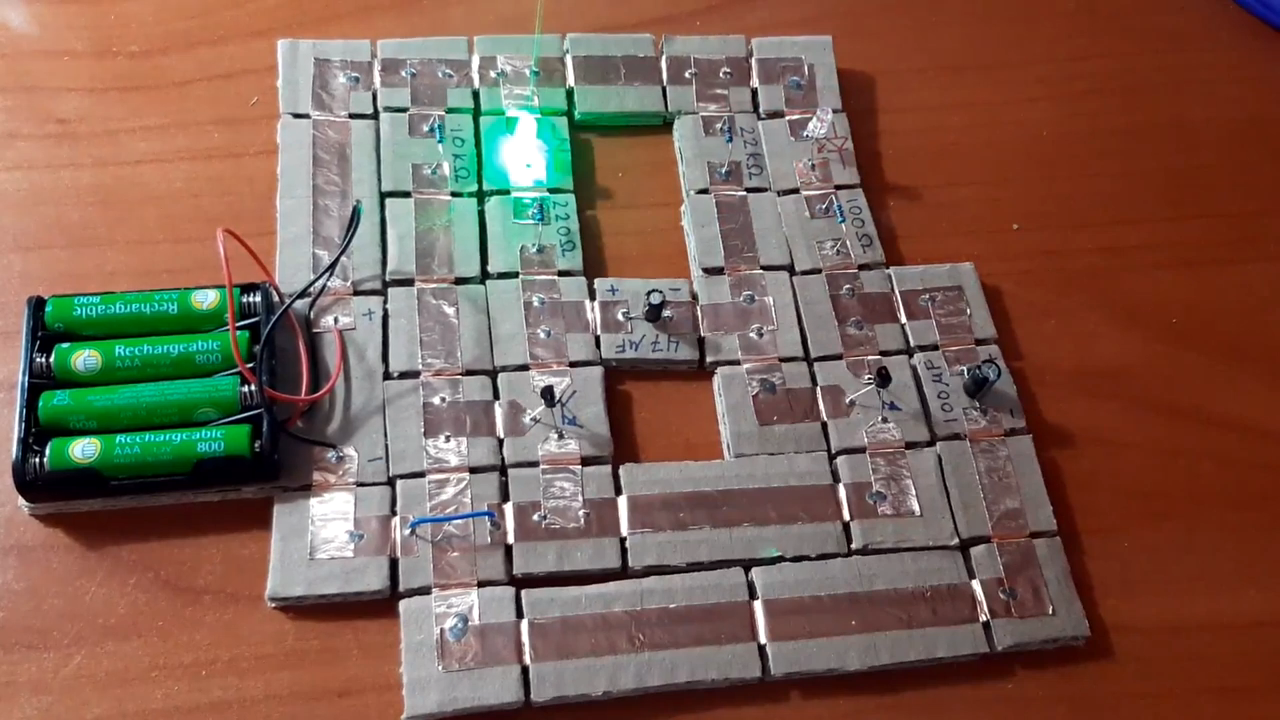

Magnetic circuits sound like something a wizard would build after getting bored with regular copper wire. In reality, they are a surprisingly practical, hands-on way to learn electronics, prototype simple ideas, and escape the spaghetti swamp that often appears on a solderless breadboard. Instead of poking jumper wires into rows of tiny holes and hoping the power rail is actually connected, magnetic circuit systems use snap-together blocks, conductive pads, magnetic connectors, or modular components that physically click into place.
That click matters. It turns electronics from a mysterious nest of red and black wires into something visible, movable, and almost playful. For beginners, educators, makers, and even experienced tinkerers who have yelled at a breadboard at least once, magnetic circuit prototyping offers a refreshing alternative. It is not a universal replacement for breadboards, perfboards, or printed circuit boards. But for teaching, experimenting, and quickly testing low-voltage circuits, it can make electronics feel less like tax paperwork with electrons and more like building with smart LEGO bricks.
This article explores why magnetic circuit blocks are attractive, how they compare with traditional breadboarding, where they shine, where they fail, and why the humble magnet may deserve a permanent spot on the electronics workbench.
What Are Magnetic Circuits in This Context?
In electrical engineering, the phrase “magnetic circuit” can also refer to the path of magnetic flux in transformers, motors, inductors, and magnetic cores. That is a real and important topic, but here we are talking about something more maker-friendly: electronic circuits assembled with magnetic connections.
A magnetic circuit prototyping system usually includes small blocks, tiles, pads, or modules. Each one holds a real electronic part such as an LED, resistor, switch, battery pack, potentiometer, speaker, capacitor, transistor, sensor, or microcontroller interface. Magnets help the pieces snap together, align correctly, and maintain contact between conductive surfaces. Some systems use cardboard or 3D-printed blocks. Others use machined modules, conductive ink, magnetic snaps, copper tape, or custom boards.
The big idea is simple: instead of hiding all the important connections inside a plastic breadboard, the circuit becomes visible. You can see where power begins, where current flows, where the LED sits, and where the switch interrupts the path. That is wonderful for learning, because the circuit stops being an abstract diagram and becomes a physical story.
Why Breadboards Are Useful but Occasionally Maddening
Before declaring magnetic systems the superhero of the lab bench, let’s be fair to the classic solderless breadboard. Breadboards are cheap, reusable, widely available, and incredibly useful. They let you build temporary circuits without soldering. Students use them. Engineers use them. Hobbyists use them. Entire Arduino starter-kit empires have been built on their tiny white plastic shoulders.
A breadboard works because metal spring clips underneath the holes connect groups of sockets together. Components and jumper wires are pushed into those holes, forming temporary electrical connections. This is excellent for simple circuits, microcontroller experiments, LED projects, button inputs, sensor testing, and early proof-of-concept work.
But breadboards also have a personality. Sometimes that personality is “helpful lab partner.” Sometimes it is “tiny plastic goblin.” Older breadboards may have loose contacts from years of abuse by thick component leads. Newer boards can grip so tightly that a freshly cut jumper wire folds like a nervous spaghetti noodle. Power rails may be split in unexpected places. Jumper wires can hide mistakes. A circuit that should work may fail because one wire is off by one row, and suddenly your afternoon has become a detective drama.
For high-frequency, high-current, precision analog, or mechanically reliable designs, breadboards also have limitations. Their internal strips add unwanted resistance, capacitance, and inductance. Those parasitic effects may not matter for a blinking LED, but they can make fast signals, sensitive amplifiers, radio circuits, and switching power projects behave strangely. In short, breadboards are brilliant for many tasks, but they are not magic carpets.
Why Magnetic Circuit Blocks Feel So Appealing
Magnetic circuit blocks solve a different problem: they make electronics easier to see, touch, rearrange, and explain. A resistor is no longer a beige mystery grain with stripes. It is a labeled block. A switch is no longer two legs jammed into a plastic grid. It is a visible control in the path. A battery is not hiding behind red and black jumper wires. It is the obvious source of the circuit.
This physical clarity is especially powerful in classrooms and beginner workshops. When learners snap together a battery, switch, resistor, and LED, they can understand cause and effect quickly. Open the switch and the LED turns off. Reverse the LED and it does not light. Add too much resistance and the LED dims. Put two LEDs in parallel and the behavior changes. The lesson becomes immediate.
Magnetic modules also reduce the intimidation factor. A solderless breadboard asks beginners to understand hidden internal connections before they even begin. Magnetic blocks, by contrast, usually make the connection path part of the design. That means fewer “Wait, why is this row connected but that row is not?” moments. The circuit behaves more like a map and less like a secret handshake.
How Magnetic Circuit Systems Usually Work
Most magnetic circuit systems share a few core design principles. They are modular, reusable, low-voltage, and visually organized. The exact construction varies, but the anatomy often looks like this:
1. A physical block or tile
The component is mounted on a small block made from cardboard, wood, acrylic, plastic, or a 3D-printed shell. The block gives the part structure and makes it easy to handle. It also provides space for labels, polarity marks, and contact points.
2. Conductive contact areas
Each block needs a way to carry electricity. Some designs use copper tape. Others use metal pads, conductive fabric, conductive thread, spring contacts, or printed traces. The goal is to create a reliable electrical connection when two pieces touch.
3. Magnets for alignment and pressure
Small magnets help blocks snap together and keep conductive surfaces pressed against each other. This improves the user experience because the circuit feels intentional. The pieces do not merely sit nearby; they click into place with a satisfying little “yes, I belong here.”
4. Clear labels and polarity
Good magnetic modules label components clearly. LEDs mark anode and cathode. Batteries show positive and negative. Switches show open and closed positions. This prevents the learning experience from becoming a guessing game hosted by an angry multimeter.
5. Reconfigurable layouts
The main benefit is quick experimentation. Want to move the switch before the LED? Snap it into a new position. Want to compare series and parallel circuits? Rearrange the blocks. Want to add a sensor or buzzer? Add another module. The circuit becomes a conversation.
Magnetic Circuits vs. Breadboarding: A Practical Comparison
| Feature | Magnetic Circuit Blocks | Solderless Breadboards |
|---|---|---|
| Beginner friendliness | Very high because connections are visible and tactile | Moderate because internal rows can confuse beginners |
| Speed of rearranging | Fast for simple modular circuits | Fast, but jumper-wire mistakes are common |
| Component flexibility | Limited to available modules unless you make your own | Very flexible for through-hole components |
| Best use case | Teaching, demonstrations, low-voltage experiments | General prototyping, microcontroller projects, circuit testing |
| Reliability | Good when magnets and contacts are well designed | Good for many projects, but contacts can loosen over time |
| High-frequency performance | Usually not intended for high-speed work | Also limited by parasitic effects |
| Fun factor | Excellent; magnets do half the charm offensive | Respectable, unless the jumper wires form a jungle |
Best Projects for Magnetic Circuit Prototyping
Magnetic circuits are strongest when the goal is learning, demonstration, and fast iteration. They are perfect for simple projects where the physical arrangement teaches the concept.
LED and switch circuits
The classic first project is a battery, resistor, switch, and LED. It teaches polarity, current flow, resistance, and the idea of an open or closed circuit. With magnetic blocks, students can physically break the circuit apart and see why the light goes out.
Series and parallel circuits
Magnetic modules make series and parallel layouts much easier to understand. Put two resistors in series and observe the effect. Move them into parallel and compare. The arrangement is visible, which helps learners connect the physical layout to the schematic.
Simple sensors
Light-dependent resistors, thermistors, tilt switches, reed switches, and potentiometers all work well in modular demonstrations. Add an LED or buzzer as the output, and the circuit becomes interactive.
Transistor switching
A transistor can be introduced as an electronic switch. With magnetic blocks, learners can see the control side and output side separately. That is far less intimidating than a three-legged component hiding in breadboard rows like a tiny plastic crab.
Audio and buzzer experiments
Small speakers, piezo buzzers, and oscillators make magnetic circuits lively. Sound gives immediate feedback, which is excellent for workshops. Nothing says “I built a circuit” quite like a buzzer making a noise that everyone else politely wishes were shorter.
Where Magnetic Circuits Are Not the Best Tool
Magnetic circuit prototyping is delightful, but it is not a replacement for every electronics method. The biggest limitation is component variety. A breadboard can accept thousands of standard through-hole parts, breakout boards, sensors, and jumper wires. A magnetic system depends on the modules you own or build.
Magnetic connections can also introduce contact resistance or intermittent behavior if the pads are dirty, misaligned, weakly magnetized, or poorly designed. For a classroom LED circuit, that may be acceptable. For a precision analog measurement circuit, it is less charming.
High-speed circuits are another weak spot. Radio-frequency designs, fast digital buses, sensitive amplifiers, and switching power supplies require careful layout, grounding, short traces, controlled impedance, and solid connections. Magnetic blocks are generally too physically large and electrically loose for that kind of work.
Current handling matters too. Small magnets and thin conductive tape are not meant for heavy loads. Motors, heaters, large LED strips, and power electronics should be approached carefully with proper wire gauges, fuses, connectors, and thermal planning. Magnetic circuits are best treated as low-voltage learning tools unless specifically engineered for more demanding use.
Why Magnetic Prototyping Fits Modern Maker Culture
The maker world loves tools that lower the barrier between idea and experiment. Arduino made microcontrollers friendlier. Conductive ink made circuits drawable. Snap-together electronic modules made sensors and outputs feel like building blocks. E-textile prototyping boards use magnetic connectors to help makers test wearable circuits before committing to stitching. Magnetic circuits belong to the same family of ideas: make the invisible visible, make the fragile reusable, and make experimentation less scary.
This is especially important because electronics can be emotionally weird for beginners. A woodworking mistake is visible. A cooking mistake is tasteable. An electronics mistake may be completely silent. Nothing moves. Nothing glows. No smoke appears, which is good, but also not very informative. Magnetic systems give learners more visual clues, helping them debug the physical circuit before diving into theory.
That does not mean theory disappears. Ohm’s law still matters. Polarity still matters. Current still needs a complete path. Resistors still limit current, capacitors still store charge, and transistors still behave like tiny gatekeepers with opinions. Magnetic blocks simply make those ideas easier to approach.
How to Build Your Own Magnetic Circuit Blocks
A simple DIY magnetic circuit block system can be made with inexpensive materials. Start with a nonconductive base such as cardboard, foam board, thin plywood, or a 3D-printed part. Add copper tape or metal contact pads along the edges. Mount a component on top and connect its leads to the contact areas. Add small magnets near the contact points so blocks align and hold together.
For a basic starter set, create modules for a battery pack, LED, resistor, switch, buzzer, potentiometer, and jumper block. Use large labels. Mark polarity clearly. Keep all circuits low voltage. Test every block with a multimeter before handing it to learners. The goal is not to create a laboratory-grade instrument; the goal is to create a friendly bridge between a schematic and a working circuit.
One helpful design trick is to make the physical shape prevent obvious mistakes. For example, power modules can use a different color or connector orientation. LED modules can display a big arrow showing current direction. Resistor modules can include the resistance value in large text. The more the object teaches by its shape, the less explaining you need to do later.
Magnetic Circuits in Education
In education, magnetic circuits are valuable because they support active learning. Students do not merely watch a teacher draw a schematic. They build, test, fail, fix, and rebuild. That process is where understanding grows.
For younger learners, magnets add a familiar physical language. Snap, separate, rotate, compare. For older learners, modular circuits can introduce schematic thinking before moving to breadboards. For teachers, magnetic blocks make demonstrations easier because the whole class can see the circuit. A breadboard may be too small to explain from across the room, but labeled blocks can be arranged on a table or whiteboard-sized surface.
There is also an accessibility benefit. Some learners struggle with tiny jumper wires and closely spaced breadboard holes. Larger magnetic pieces can be easier to handle, especially in group settings or introductory labs. The result is less frustration and more time spent on actual concepts.
The Ideal Workflow: Magnets, Breadboards, Then PCBs
The smartest approach is not to choose one prototyping method forever. It is to use the right tool at the right stage.
Start with magnetic circuits when the goal is understanding. Use them to teach current flow, switching, polarity, series circuits, parallel circuits, and basic component behavior. Move to a solderless breadboard when the design needs more components, integrated circuits, microcontrollers, sensors, and flexible wiring. Move to perfboard, solderable breadboard, or a custom PCB when the project needs durability, compactness, repeatability, or better electrical performance.
In other words, magnetic circuits are the friendly front door. Breadboards are the workshop. PCBs are the finished architecture. Each has a place, and each becomes more useful when you understand its strengths.
Experience Notes: What Magnetic Circuits Feel Like in Real Prototyping
The first experience most people have with magnetic circuits is not technical. It is emotional. The pieces snap together, and suddenly the circuit feels less like homework. That may sound minor, but it changes the rhythm of learning. With a traditional breadboard, the beginner often pauses to count holes, trace hidden rows, check rail gaps, and wonder whether the red wire is in the same node as the resistor lead. With magnetic blocks, the question becomes simpler: “Is the path complete?” That is a better first question.
In a workshop setting, magnetic circuits also encourage experimentation. Someone can build a working LED circuit, then immediately ask, “What happens if I add another LED?” Instead of dismantling a nest of jumpers, they snap in another module. If it fails, the failure is visible. Maybe the LED is reversed. Maybe the resistor value is too high. Maybe the circuit path is broken. The learner can physically point to the problem, which makes debugging feel less like guessing and more like solving a puzzle.
Another practical advantage is cleanup. Breadboard sessions often end with jumper wires scattered like confetti after a robot birthday party. Magnetic modules are easier to count, sort, and store. For teachers, parents, or club organizers, that matters. A tool that reduces setup and cleanup time gets used more often. A tool that lives in a box of tangled wires slowly becomes a museum exhibit titled “Good Intentions, 2024.”
Magnetic circuits also reveal how much physical design influences learning. When the battery block is large and labeled, students respect it as the source. When the resistor block sits visibly before an LED, current limiting becomes easier to discuss. When a switch physically opens the path, the abstract idea of continuity becomes obvious. This is where magnetic blocks outperform a plain breadboard: they turn layout into explanation.
However, the experience is not perfect. Weak magnets can make connections unreliable. Copper tape can wrinkle. Exposed contacts can oxidize or collect dirt. If the blocks are too large, complex circuits become awkward. If the magnets are too strong, young builders may pull components loose while separating modules. A good magnetic circuit kit needs thoughtful mechanical design, not just electronics knowledge.
The best results come when magnetic circuits are treated as a learning and ideation tool, not as a final engineering platform. They are excellent for “What does this component do?” and “How does this circuit path work?” They are less appropriate for “Will this 2 MHz amplifier behave exactly like my simulation?” That is not a failure. A bicycle is not bad because it cannot tow a cargo ship. It simply has a different job.
After using magnetic-style prototyping, many learners transition to breadboards with more confidence. They already understand complete paths, polarity, inputs, outputs, and component order. The breadboard is still a little sneaky, but it is no longer a haunted rectangle. That may be the real attraction: magnetic circuits do not eliminate breadboarding; they make people less afraid of it.
Conclusion
Magnetic Circuits Are More Attractive Than Breadboarding because they make electronics visible, tactile, and beginner-friendly. They reduce the confusion of hidden breadboard connections, encourage fast experimentation, and help learners understand circuits as physical systems rather than mysterious diagrams. For classrooms, maker spaces, STEM kits, and early concept demonstrations, magnetic circuit blocks are a genuinely useful alternative.
Still, breadboards remain essential. They support more components, more flexible layouts, and a wider range of real prototyping tasks. The point is not that magnets defeat breadboards in a dramatic lab-bench duel. The point is that magnetic circuits offer a better first step for many learners and a more playful way to explore simple electronics. Once the concept is clear, breadboards and PCBs can take the project further.
So yes, magnetic circuits are attractive. Literally, because magnets. Practically, because they make learning easier. And emotionally, because every satisfying snap says, “Congratulations, your circuit is one step closer to working, and your jumper wires can stop auditioning for a bowl of noodles.”
Note: This article is synthesized from real electronics prototyping principles and reputable engineering, education, and maker references. Source links are intentionally excluded from the HTML body for clean web publishing.