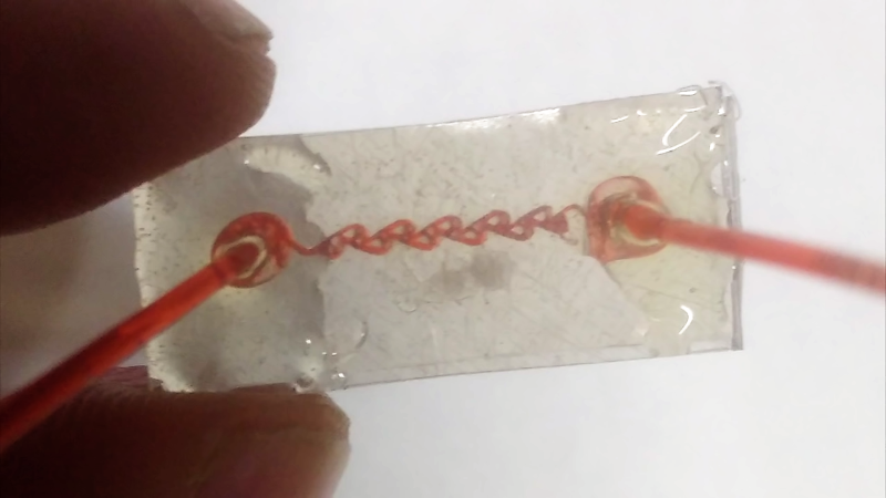

Microfluidics sounds like something that should happen behind a glass wall, guarded by a person in a lab coat who knows exactly where the expensive tweezers are kept. In reality, the basic idea is beautifully simple: move tiny amounts of liquid through tiny channels and use those channels to mix, sort, test, react, or measure something. Think of it as plumbing for ants, except the ants are biomedical engineers and the pipes may someday help diagnose disease, grow cells, test chemicals, or run portable lab-on-a-chip devices.
Now for the twist: one of the cleverest shortcuts in this field came from a children’s craft material. Yes, Shrinky Dinksthe plastic sheets that kids color, bake, and turn into miniature charmshave been used to simplify microfluidic chip fabrication. That may sound like science wandered into a craft store and got distracted, but it is a real and surprisingly powerful idea. By using shrink film’s tendency to contract when heated, researchers and makers can create smaller, deeper, more useful microchannels from larger, easier-to-machine designs.
The result is a low-cost microfluidics method that swaps some of the traditional cleanroom complexity for printers, cutters, ovens, PDMS, and a healthy respect for temperature control. It is not magic. It is materials science wearing a craft apron.
What Is Microfluidics, Really?
Microfluidics is the science and engineering of controlling very small volumes of liquids or gases inside channels that are often tens to hundreds of micrometers wide. At that scale, fluids behave differently than they do in a kitchen sink or garden hose. Flow is usually smooth and predictable, mixing can be slow unless the channel is designed cleverly, and surface effects become a very big deal.
That last part is important. In the macro world, gravity acts like the boss. In the micro world, capillary forces, viscosity, surface tension, and channel geometry start walking around with clipboards. This is why microfluidic chips can do things that look almost electronic: guide flow, split samples, create gradients, sort cells, generate droplets, or run assays using only tiny amounts of fluid.
Why Lab-on-a-Chip Devices Matter
A lab-on-a-chip device is exactly what the name suggests: a miniaturized platform that can perform one or more lab functions on a small chip. These devices are valuable because they can reduce sample volume, shorten reaction time, lower reagent costs, and make certain tests more portable. In medicine, microfluidic devices are studied for point-of-care diagnostics, blood analysis, infectious disease testing, cancer research, and organ-on-chip systems. In chemistry and materials science, they can help with controlled reactions, droplet production, particle analysis, and high-throughput experiments.
The catch is fabrication. Traditional microfluidic devices often rely on photolithography, silicon wafers, cleanrooms, plasma treatment, precise bonding, and specialized equipment. Those tools are amazing, but they are not exactly “weekend project on a folding table” friendly. For universities, startups, classrooms, and small labs, the cost and turnaround time can slow down experimentation.
That is where shrink film enters the story with the confidence of a toy that accidentally earned a graduate degree.
The Shrinky Dinks Trick: Big Pattern In, Tiny Channel Out
Shrinky Dinks are made from shrinkable polystyrene film. When heated, the sheet contracts in length and width while becoming thicker and more rigid. That physical transformation is the whole trick. Instead of trying to carve a tiny microchannel directly at the final size, you create a larger version of the pattern first. Then heat does the miniaturizing.
In early research, engineers printed patterns onto the shrink film using a laser printer. As the plastic sheet shrank, the printed toner features tightened, rose, and became useful as a mold. A liquid polymer such as PDMSpolydimethylsiloxane, the clear rubbery superstar of soft lithographycould then be poured over the shrunken pattern. Once cured and peeled away, the PDMS contained microchannels shaped by the raised features.
In maker-style versions, the same concept can be adapted by machining or inscribing grooves into the shrink film. A CNC mill, craft cutter, blade, or other controlled cutting method creates larger channels in the sheet. After baking, those grooves shrink laterally and deepen relatively, producing channels that are closer to microfluidic dimensions. Multiple layers can be stacked to create more complex circuits.
Why Shrinking Helps
The genius of the approach is that it uses shrinkage as a resolution booster. A tool that cannot reliably cut a very tiny feature may still cut a larger version of that feature. After shrinking, the feature becomes smaller without requiring a more expensive tool. It is like drawing a map on a balloon, then deflating itexcept the material thickens, the dimensions change, and ideally nobody in the lab is chasing a balloon under the bench.
This means a design can start in CAD software, be printed or cut at a manageable scale, and then be reduced through heating. For rapid prototyping, that is a big deal. Researchers can test several channel layouts quickly instead of waiting days or weeks for conventional molds.
From Kitchen Hack to Serious Bioengineering
The best-known Shrinky-Dink microfluidics work is associated with biomedical engineer Michelle Khine and collaborators, who showed that shrinkable polystyrene sheets could be used to make molds for PDMS microfluidic devices. The approach demonstrated rounded channels, multi-height features, and microchannels suitable for cell-related applications. One of the reasons the method became famous is that it made sophisticated microfluidic prototyping feel less locked behind expensive infrastructure.
That story is also a reminder that scientific innovation is not always a straight march through polished equipment catalogs. Sometimes it starts with a bottleneck, a lack of cleanroom access, and a childhood memory of plastic sheets curling in an oven. The glamorous term is “resourceful engineering.” The more honest term is “making the equipment you have behave like the equipment you wish you had.”
What Can Shrinky-Dink Microfluidics Make?
Simple shrink-film microfluidic systems can be used to demonstrate classic chip functions, such as Y-junction channels, mixers, droplet generators, gradient generators, cell-flow channels, and directional-flow structures. A Tesla valve, for example, can be created as a passive flow-control element that favors flow in one direction more than the other. In electronics language, people sometimes compare it loosely to a diode, though liquids have their own stubborn personality.
For education, this is especially powerful. Students can see that microfluidics is not abstract. It is fluid moving through a designed path. A channel can split, merge, narrow, widen, swirl, resist, or mix. Add food dye and the lesson becomes visible. Add a microscope and suddenly the small world stops being theoretical.
For research and prototyping, the value is speed. A lab can test whether a channel geometry works before committing to a more expensive fabrication process. Not every prototype needs to be perfect. Sometimes it just needs to answer the question, “Is this design worth pursuing?” Shrink film is good at helping researchers ask that question quickly.
How the Basic Fabrication Workflow Works
The exact workflow depends on whether the shrink film is used as a mold or as the device itself. Both approaches have been explored.
Method One: Shrink Film as a Mold for PDMS
In the mold-based method, the designer creates a microchannel layout in CAD software. The design is printed, cut, engraved, or otherwise patterned onto shrink film at a larger scale. The sheet is then heated under controlled conditions. As it shrinks, the features become smaller and more pronounced. PDMS is poured over the patterned film, cured, and peeled away. The PDMS layer is then bonded to glass, another PDMS layer, or a suitable substrate to seal the channels.
This approach is appealing because PDMS is transparent, flexible, and widely used in microfluidics. It is compatible with many imaging setups, which matters when researchers want to watch cells, droplets, or particles move through a channel. The shrink film does the mold-making job; PDMS becomes the final device.
Method Two: Shrink Film as the Microfluidic Chip
Another approach is to inscribe the microchannels directly into the shrink film, bake it, and thermally bond it to another piece of shrink film as a cover layer. This can eliminate casting and reduce the number of steps. Recent work has explored using cutters and manual tools to create channel patterns, then bonding layers to create sealed devices.
The advantage is simplicity. The challenge is control. Shrink film can warp, channel walls can collapse or stick, and surface roughness can affect fluid flow. Temperature, baking time, pressure, flatness, and cleaning all matter. This is the part where the craft-store miracle becomes less like a magic trick and more like engineering: repeatability must be earned.
Advantages of Shrinky-Dink Microfluidics
The biggest advantage is accessibility. A method that uses affordable shrink film, common design software, a printer or cutter, and an oven can open microfluidic prototyping to labs and classrooms that do not have cleanroom access. That does not replace professional microfabrication, but it changes who can start experimenting.
The second advantage is rapid iteration. Microfluidics often requires trial and error. A channel may look perfect on the screen but behave oddly once fluid starts moving. Maybe bubbles get trapped. Maybe two streams refuse to mix. Maybe a channel is too shallow, too rough, or too ambitious for the available pump. With shrink-film prototyping, design changes can be made quickly, tested, and revised.
The third advantage is educational clarity. Shrink-film devices make microfluidics less intimidating. Students can connect CAD design, material behavior, heating, bonding, and fluid testing in one workflow. The process is tactile and visual, which is rare in a field that can otherwise feel like a parade of acronyms wearing safety goggles.
Cost and Speed
Traditional microfluidic fabrication can be expensive because it may require photomasks, wafers, cleanroom time, spin coating, UV exposure, chemical development, plasma bonding, and trained personnel. Shrink-film methods reduce that barrier. They are particularly useful when the goal is proof-of-concept rather than mass production.
Speed matters because design thinking works best when feedback is fast. If every idea takes weeks to fabricate, researchers become cautious. If a prototype can be made quickly, people explore more designs. Some of those designs will fail spectacularly, but in science, a cheap failure is often a useful failure. It is the expensive failures that make everyone stare silently at the coffee machine.
Limitations You Should Not Ignore
Shrinky-Dink microfluidics is clever, but it is not perfect. Shrink film can deform unevenly during heating. Feature dimensions may vary depending on oven temperature, heating time, sheet brand, orientation, and how the material is held flat. Surface roughness can influence flow resistance, and bonding can be tricky if channels are too small or too close together.
Resolution is another limitation. Shrinking improves feature size, but it does not grant infinite precision. If the initial pattern is messy, the shrunken version becomes a smaller messy pattern. Printer artifacts, cutter burrs, dust, and uneven grooves can all show up in the final chip. Microfluidics is very good at revealing small mistakes. It is basically a microscope with plumbing.
There are also material compatibility questions. Polystyrene and PDMS do not behave like glass, silicon, or specialized thermoplastics. Some chemicals may swell, absorb, leach, or interact with device materials. Biological assays may need surface treatment to improve wetting, reduce nonspecific adsorption, or support cell behavior. Plasma treatment and coatings can help, but they add complexity.
Best Uses for Shrink-Film Microfluidics
Shrink-film microfluidics is best for rapid prototyping, demonstrations, educational labs, proof-of-concept devices, simple mixers, droplet tests, channel geometry studies, and early-stage design exploration. It is less suitable when a project needs highly uniform nanoscale features, strict regulatory manufacturing standards, aggressive chemical compatibility, or long-term industrial durability.
In other words, Shrinky Dinks can help you learn, iterate, and prototype. They should not be treated as a universal replacement for every microfabrication method. A toaster oven is useful, but it is not a cleanroom with a crumb tray.
Why This Approach Still Matters Today
Microfluidics has grown far beyond simple channels. Modern lab-on-a-chip systems can integrate sensors, valves, electronics, optical detection, droplet generation, cell culture chambers, and automated sample preparation. Yet one persistent problem remains: building and testing devices can be too slow and too expensive for many teams.
Shrink-film microfluidics matters because it pushes the field toward accessibility. It says that good ideas should not always have to wait for perfect infrastructure. It also encourages a practical mindset: use the physics of the material instead of fighting it. Shrinkage is usually considered a manufacturing headache. Here, it becomes the manufacturing strategy.
This approach also fits the broader maker movement in science. Desktop cutters, 3D printers, low-cost microscopes, open-source syringe pumps, and affordable microcontrollers have changed what small labs and students can build. Shrink film belongs to that same toolbox. It lowers the first step, and sometimes that first step is the difference between reading about microfluidics and actually making fluid move through a chip you designed yourself.
Specific Examples of Shrinky-Dink Microfluidic Designs
A simple Y-channel is one of the easiest examples. Two inlet channels merge into one outlet channel, allowing two colored fluids to meet. At normal size, the pattern may look almost boring. After shrinking and sealing, it becomes a visual lesson in laminar flow. The streams travel side by side, and mixing depends mainly on diffusion unless the design includes structures that disturb the flow.
A gradient generator is more advanced. It splits and recombines streams through a branching network, producing different concentrations at multiple outlets. In cell biology, gradient generators can expose cells to controlled chemical environments, helping researchers study migration, drug response, or signaling behavior.
A droplet generator uses channel geometry and two immiscible fluids, such as oil and water, to create droplets. These droplets can act like tiny reaction vessels. Droplet microfluidics has applications in chemistry, biology, materials science, and screening assays. A shrink-film prototype can demonstrate the concept without requiring a full industrial setup.
A Tesla valve design is another fun example. It uses geometry to create direction-dependent flow resistance without moving parts. In microfluidics, passive flow-control features are attractive because moving mechanical valves become harder to build and operate at small scales.
Practical Experiences and Lessons From Working With Shrink-Film Microfluidics
The first experience many people have with shrink-film microfluidics is surprise. The material looks too ordinary to do anything serious. A flat plastic sheet, a cutter, and an oven do not scream “biomedical engineering.” Then the sheet shrinks, the channels change shape, and suddenly the idea makes sense. The process feels playful, but the physics is real.
A common lesson is that temperature control matters more than expected. Ovens have hot spots. A sheet placed too close to a heating element may curl or distort. A sheet heated without a flat weight or smooth support may warp. The best results usually come from treating the baking step as a controlled process, not as a casual snack-prep activity. Preheat the oven, keep heating time consistent, use a clean flat surface, and record what works. The lab notebook should not say “baked until it looked science-y.”
Another practical lesson is that channel design should be forgiving. Beginners often design channels that are too narrow, too sharp, or too close together. After shrinking, those features can clog, merge, or collapse. Wider channels, smoother curves, and generous spacing are more reliable for early tests. Once the basic workflow is working, the design can become more ambitious.
Cleaning is also more important than it sounds. Dust, plastic debris, fingerprints, and cutting residue can interfere with bonding and flow. A tiny particle that would be invisible on a normal craft project can become a major obstruction in a microchannel. In microfluidics, lint behaves like a boulder with a public relations team.
Bonding teaches patience. If two layers do not seal properly, fluid will leak or creep between surfaces. If the bonding pressure is too high or the channel design too delicate, the channel may flatten. Finding the balance between sealing and preserving geometry is part of the learning curve. This is why test pieces are valuable. Before making a complicated chip, it helps to bond a simple straight channel and run colored water through it.
Fluid testing brings its own comedy. Bubbles appear from nowhere. Syringe connections leak at exactly the wrong moment. A beautiful channel may refuse to fill because the surface is too hydrophobic. Flow may look perfect for ten seconds and then stop because a tiny air pocket parked itself like an unlicensed truck in the outlet. These are not failures of the concept. They are normal microfluidic realities. Surface treatment, careful priming, degassed fluids, better tubing connections, and slower flow rates can help.
One rewarding experience is watching two streams of dye meet in a transparent channel. It is simple, but it makes microfluidics instantly understandable. The flow does not tumble like water in a river. It glides. The colors sit beside each other until diffusion slowly softens the boundary. That moment explains more than a page of equations for many learners.
The biggest lesson is that shrink-film microfluidics rewards iteration. The first chip may warp. The second may leak. The third may work but look like it was designed by a nervous spaghetti noodle. By the fourth or fifth attempt, patterns emerge: better corners, cleaner cuts, improved baking, more reliable sealing. The process becomes less mysterious. That is the real value. Shrinky Dinks do not merely make microfluidics cheaper; they make it approachable enough for people to learn by doing.
Conclusion: Small Channels, Big Shortcut
Making microfluidics simpler with Shrinky Dinks is not just a cute science story. It is a smart example of using material behavior to solve a fabrication problem. Shrink film takes patterns that are easy to draw, print, cut, or machine at a larger scale and reduces them into useful microfluidic features. That makes rapid prototyping faster, cheaper, and more accessible.
The method has limitations, especially in precision, flatness, bonding, roughness, and chemical compatibility. But for education, early-stage design, proof-of-concept devices, and creative experimentation, it is a powerful tool. It lowers the barrier to entry in a field that too often looks expensive from the outside.
In the end, Shrinky-Dink microfluidics proves that innovation does not always require the fanciest equipment in the building. Sometimes it requires curiosity, a toaster oven, a sheet of polystyrene, and the willingness to ask a delightfully dangerous question: “What happens if we bake the prototype?”
SEO Tags