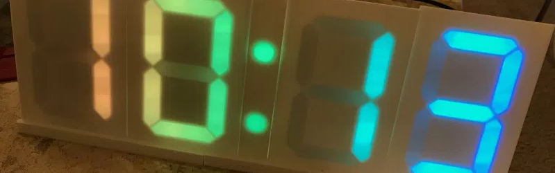

There are clocks that tell time, and then there are clocks that announce it with glowing confidence, like a tiny nightclub for your workbench. A color changing clock that uses PCB digits sits proudly in the second category. It is not just a digital clock with LEDs slapped behind a plastic faceplate. It is a clever electronics project where the digits themselves are built from printed circuit boards, addressable RGB LEDs, and a good old seven-segment display layout.
At first glance, the idea sounds simple: make a clock, make it colorful, make it readable. But the charm is in the engineering. Instead of using off-the-shelf seven-segment modules, the maker approach uses custom PCBs as the physical structure for each digit. LED strips or individual addressable LEDs are arranged into the familiar seven bars that form numbers from 0 to 9. A microcontroller drives the colors, timekeeping hardware keeps the hours honest, and the PCB becomes both the skeleton and the stage. In other words, the circuit board is not hiding inside the clock; it is the clock’s personality.
What Is a PCB Digit Clock?
A PCB digit clock is a digital clock that uses printed circuit boards as the visible digit modules. Each digit is typically shaped around the classic seven-segment display, the same display logic used in calculators, alarm clocks, fuel pumps, and microwave ovens. Seven separate segments can be turned on or off in different combinations to create numbers. Light up the top, upper-right, lower-right, bottom, lower-left, and upper-left segments, and you get a zero. Light up only the right-side segments, and there is your one, standing there like it forgot leg day.
The difference here is that the digit is not a sealed commercial component. It is built from a custom PCB, which may hold RGB LED strips, surface-mounted addressable LEDs, resistors, connectors, and sometimes even the controller circuitry. In one well-known maker design, multiple copies of a single circuit board are used for each digit. Only the first board needs the microcontroller and time-driving electronics, while the remaining boards act as repeatable digit modules. That modular strategy is smart because it reduces design work, simplifies assembly, and makes the final clock easier to expand or repair.
Why PCB Digits Are So Appealing
The biggest reason PCB digits are fun is that they turn a normally invisible part of electronics into the star of the design. Most consumer gadgets try to hide circuit boards under plastic shells. Makers, however, often look at a PCB and see beauty: copper traces, solder mask colors, silkscreen labels, vias, pads, and perfectly lined-up components. A clock made from PCB digits says, “Yes, I am a circuit board, and yes, I look fabulous.”
PCB digits also solve practical problems. A custom board can provide accurate LED placement, clean power routing, repeatable mounting holes, and tidy connector paths. Instead of hand-gluing LED strips into a frame and hoping everything lines up, the PCB defines the geometry. That matters because seven-segment clocks depend heavily on visual consistency. If one segment leans slightly to the left like it heard bad news, the whole clock starts to look homemade in the wrong way.
How the Color Changing Effect Works
The color changing magic usually comes from addressable RGB LEDs, often known by names such as NeoPixel, WS2812B, SK6812, or similar LED families. Unlike ordinary single-color LEDs, addressable RGB LEDs include tiny control circuitry. Each LED can receive digital instructions and display a specific color. Because red, green, and blue light can be mixed at different brightness levels, the clock can show thousands or millions of possible color combinations.
That means the clock is not limited to one boring glow. It can fade from blue to purple, flash red at midnight, shift to warm amber at night, or run a rainbow animation when the maker feels dangerously festive. The LEDs are commonly controlled with a single data line from a microcontroller, while power and ground lines feed the entire chain. The result is a surprisingly simple wiring scheme for something that looks visually complex.
Segments, Pixels, and Patterns
In a PCB digit clock, each segment may contain several LEDs. For example, the top segment of a digit might use three or five addressable LEDs, depending on the size of the clock. The software groups those LEDs into a logical segment. When the clock needs to show the number “2,” it turns on the top, upper-right, middle, lower-left, and bottom segments. If the display is color changing, the software also decides what color those segments should be.
This is where the project becomes more than just a clock. The software can treat each digit, segment, or even individual LED as part of an animation canvas. The hour digits can glow one color while the minute digits glow another. The colon can pulse once per second. The whole display can dim after bedtime. The clock can even change color based on time of day, room mood, weather data, or an alarm state. Suddenly, your clock has opinions.
The Role of the Microcontroller
A color changing PCB digit clock needs a brain, and that usually means a microcontroller. Popular choices include Arduino-compatible boards, ESP8266 modules, ESP32 boards, ATtiny chips, Raspberry Pi Pico boards, and other small embedded controllers. The microcontroller handles three essential jobs: keeping or receiving time, converting that time into display digits, and sending color data to the LEDs.
For a basic version, an Arduino-style controller can read time from a real-time clock module and update the display once per second. For a Wi-Fi version, an ESP32 or ESP8266 can connect to the internet and synchronize time using Network Time Protocol. NTP-based clocks are convenient because they can automatically correct drift and adjust after power interruptions, though they do depend on network availability. A real-time clock module, on the other hand, keeps ticking even when the main project is unplugged, usually with help from a coin-cell battery.
Real-Time Clock vs. Internet Time
Timekeeping is one of those details people ignore until the clock says it is 3:84 in the afternoon. A reliable clock project needs a sensible time source. A DS3231 real-time clock is a popular choice because it integrates a temperature-compensated crystal oscillator and battery backup. That makes it much more accurate than relying on a microcontroller’s internal timing alone.
Internet time is another strong option. Wi-Fi microcontrollers can fetch time from NTP servers, which are designed for synchronizing computers and devices. For a wall clock in a connected home, NTP is convenient and low-maintenance. For a clock that should keep working in a workshop, classroom, cabin, or anywhere the Wi-Fi behaves like a moody raccoon, an RTC module is the safer choice. Many advanced builds combine both: NTP for automatic correction and RTC backup for offline reliability.
Why Use One PCB Design for Multiple Digits?
One elegant feature of many PCB digit clock designs is the use of a repeated board. Instead of designing separate PCBs for each digit, the maker creates one board that can act as any digit in the clock. Four identical boards can display hours and minutes. Add two more and the clock can show seconds. This approach is efficient, inexpensive, and very maker-friendly.
Repeating one PCB design also reduces manufacturing risk. When a board is tested and works, ordering more copies is straightforward. It also makes troubleshooting easier because every digit follows the same wiring pattern. If one digit behaves badly, the builder can compare it directly with the others. Electronics repair becomes less like detective work and more like asking, “Which identical twin is blinking weirdly?”
PCB Design: Where Art Meets Routing
Designing the PCB is one of the most satisfying parts of the project. Tools such as EasyEDA, KiCad, and other electronics design platforms allow makers to draw schematics, place components, route copper traces, generate Gerber files, and send the board to a manufacturer. For this type of clock, the board layout is not just technical; it is visual design.
The maker must consider segment shape, LED spacing, mounting holes, connector placement, board size, solder mask color, and how the clock will look from across a room. A black PCB with diffused RGB LEDs can feel modern and sleek. A white board can bounce light more evenly. A red, blue, or purple board can add personality before the LEDs even turn on. The silkscreen layer can label connections or add decorative details. In short, the PCB is both circuit and canvas.
Diffusion Matters More Than You Think
Raw RGB LEDs are bright, sharp, and sometimes a little aggressive. Without diffusion, each LED can appear as a separate dot, which may look less like a polished clock and more like a robot’s dental chart. Diffusers soften the light and help each segment appear as a continuous bar. Makers often use acrylic, 3D-printed translucent covers, frosted plastic, paper, resin, or carefully spaced LED channels to spread the glow.
The best diffusion method depends on the clock’s size. A large wall clock may need more distance between LEDs and diffuser material. A compact desktop version can use thin translucent acrylic. The goal is readability. Fancy animations are delightful, but if nobody can tell whether it is 8:30 or 3:88, the clock has become modern art with a punctuality problem.
Power Planning for RGB Clock Projects
Addressable LEDs can draw significant current, especially when many of them are set to full-brightness white. A small clock may run happily from USB power, while a large display may need a dedicated 5V power supply. Makers should estimate current draw before building. A common rule of thumb is to plan for the worst case, even if the finished animation rarely uses full brightness. Power supplies enjoy being prepared. They do not enjoy surprises.
Good wiring practices matter. The microcontroller and LED power supply should share a common ground. Long LED runs may need power injection at multiple points to prevent voltage drop, which can cause dimming or color shifting. A data-line resistor and a capacitor across the LED power input are often recommended in addressable LED projects to reduce noise, spikes, and strange behavior. When LEDs start flickering randomly, it is usually not ghosts. It is wiring, power, grounding, or all three wearing a trench coat.
Software: Turning Time Into Light
The software for a PCB digit clock can be surprisingly elegant. First, the program gets the current time. Next, it separates the time into digits: tens of hours, ones of hours, tens of minutes, and ones of minutes. Then it looks up the segment pattern for each number. Finally, it sends color data to the LEDs that correspond to active segments.
A typical seven-segment lookup table maps each digit to seven on-or-off values. The number “1” lights two segments. The number “8” lights all seven. The number “4” lights four segments. Once the basic digit mapping works, the creative layer begins. The code can add gradients, fades, palette cycling, alarms, brightness schedules, and special effects. A clock that simply displays time is useful. A clock that glows like a tiny aurora while doing it is useful and emotionally supportive.
Color Modes That Make Sense
Not every color animation improves a clock. Some effects are beautiful for five minutes and irritating forever. The best color changing clock modes balance personality with readability. A slow gradient across the digits works well because it adds motion without making the numbers hard to read. A gentle pulse on the colon can show that the clock is alive. A warm dim mode at night keeps the display comfortable in a bedroom. A bright, high-contrast mode helps in a workshop or classroom.
Practical color themes can also communicate information. Blue tones can indicate nighttime. Orange can mark morning. Red can highlight an alarm. Green can show a timer completion. Purple can mean the clock has entered “because I felt like it” mode, which is a perfectly valid engineering requirement in hobby electronics.
Common Build Challenges
The most common challenge is LED mapping. If the physical LED order does not match the software’s expected order, digits may light up incorrectly. The fix is careful documentation. Label every segment, define every LED index, and test one digit before assembling the whole clock. Future you will be grateful. Future you may even stop muttering at past you.
Another challenge is brightness. RGB LEDs can be dazzling, especially indoors. Software brightness control is essential. Many addressable LED libraries support global brightness settings, but makers should also consider color choices. Pure white at full brightness can be intense and power-hungry. Softer colors often look better and use less current.
Heat is another consideration. A dense LED build running at high brightness can get warm. Good power budgeting, reasonable brightness limits, and adequate spacing help. For most desk-clock builds, heat is manageable, but large wall clocks deserve extra attention.
Why This Project Is Great for Makers
A PCB digit clock is a near-perfect intermediate electronics project because it combines several useful skills. Builders learn PCB design, LED control, soldering, embedded programming, timekeeping, power management, and enclosure design. The result is also genuinely useful. Unlike some projects that end their lives in a drawer next to three mystery cables and a heroic amount of dust, a clock can live on a wall or desk and do its job every day.
It is also easy to customize. Want huge digits? Scale the PCB. Want a minimalist version? Use fewer LEDs and a clean enclosure. Want a cyberpunk clock that looks like it belongs in a spaceship maintenance bay? Choose a dark solder mask, exposed hardware, and animated cyan-purple gradients. The basic architecture is flexible enough to support all of it.
Specific Example: A Modular Four-Digit Build
Imagine a four-digit clock for hours and minutes. Each digit PCB contains seven LED segments, with three addressable LEDs per segment. That means 21 LEDs per digit, or 84 LEDs total for four digits, plus two LEDs for the colon. The first digit board contains the microcontroller connector, power input, and possibly the RTC module. The other boards connect in a chain, passing power, ground, and data from one digit to the next.
The software defines a segment map for each digit board. At 12:45, the program lights the correct segments for 1, 2, 4, and 5. It applies a color palette, perhaps a warm sunrise gradient in the morning and a cooler blue palette at night. A brightness schedule dims the clock between 10 p.m. and 7 a.m. If Wi-Fi is available, the clock syncs time automatically. If not, the RTC keeps it running. The final result is polished, practical, and just nerdy enough to make guests ask questions.
Experience Notes: What Building a PCB Digit Clock Teaches You
Building or experimenting with a color changing PCB digit clock is a reminder that small design choices matter. The first lesson is that readability beats spectacle. It is tempting to create wild rainbow animations, chase effects, and color storms. Those effects are fun during testing, but day-to-day use rewards restraint. A slow color fade usually looks better than a display that behaves like it drank six espressos and discovered dance music.
The second lesson is that planning the LED index map early saves enormous frustration. When working with addressable LEDs, every physical LED has a position in the data chain. If you place the LEDs casually and sort it out later in code, the code becomes a spaghetti dinner with semicolons. A better approach is to design the PCB with a clear segment order, then document that order in the silkscreen or build notes. Segment A, segment B, segment C, and so on should be obvious before solder touches copper.
The third lesson is that power issues can masquerade as software problems. A clock may flicker, freeze, show random colors, or reset when too many LEDs turn on. Beginners often blame the code first, but the culprit is frequently voltage drop, weak USB power, missing common ground, or thin wires. Testing the display at low brightness first is a smart move. Once the logic works, brightness can be increased gradually while watching for instability.
The fourth lesson is that diffusion transforms the project. Bare LEDs can look harsh, especially when they are arranged in straight bars. Adding a diffuser makes the digits feel finished. Even a simple frosted acrylic layer can upgrade the look dramatically. The goal is to hide the individual light points while preserving the crisp shape of each segment. It is similar to good lighting in a restaurant: nobody wants to see the bulb, but everyone appreciates the glow.
The fifth lesson is that modularity is your friend. Reusing one PCB for every digit is not just efficient; it creates confidence. If one module works, the rest should work the same way. It also makes the clock easier to scale. A builder can start with a four-digit HH:MM version and later add seconds, temperature, countdown mode, or decorative side panels. A modular PCB design invites experimentation without forcing a complete redesign every time inspiration strikes.
The sixth lesson is that clocks are emotionally satisfying projects. A sensor gadget may sit quietly until data is needed, but a clock is always present. It becomes part of the room. When it changes color smoothly at sunset or glows softly on a desk at night, it feels less like a circuit and more like a tiny piece of functional decor. That is the best kind of maker project: useful enough to keep, personal enough to show off, and educational enough to make the next project better.
Conclusion
A color changing clock that uses PCB digits is more than a flashy timepiece. It is a compact lesson in electronics design, LED control, timekeeping, and visual craftsmanship. By turning printed circuit boards into the actual digit structure, the project celebrates the beauty of the hardware instead of hiding it. Addressable RGB LEDs bring the color, the microcontroller brings the logic, and good PCB design brings the whole idea together.
For makers, this project offers the perfect balance of challenge and reward. It is approachable, customizable, and practical. It teaches real skills without feeling like homework, unless your homework usually glows purple and tells time. Whether built as a desktop conversation piece, a wall-mounted workshop clock, or a gift for someone who appreciates beautifully nerdy objects, PCB digit clocks prove that timekeeping can be both precise and playful.
Note: This article was written for web publishing and synthesized from reputable maker, electronics, PCB design, LED control, and timekeeping references, including practical documentation and project examples from established electronics communities and component guides.