
Copying an angle without measuring it may sound like a geometry party trick, but it is a classic compass-and-straightedge construction with a solid mathematical foundation. Once you understand what the arcs are doing, the process becomes surprisingly simpleand far less mysterious than the collection of pencil marks might suggest.
This guide explains how to construct an angle congruent to a given angle in 12 clear steps. It also covers the proof behind the construction, common mistakes, practical examples, and lessons that make the technique easier to master.
What Does It Mean to Construct a Congruent Angle?
Two angles are congruent when they have exactly the same measure. They may face different directions, appear in different locations, or have sides drawn to different lengths. None of those visual differences matters. If their openings are equal, the angles are congruent.
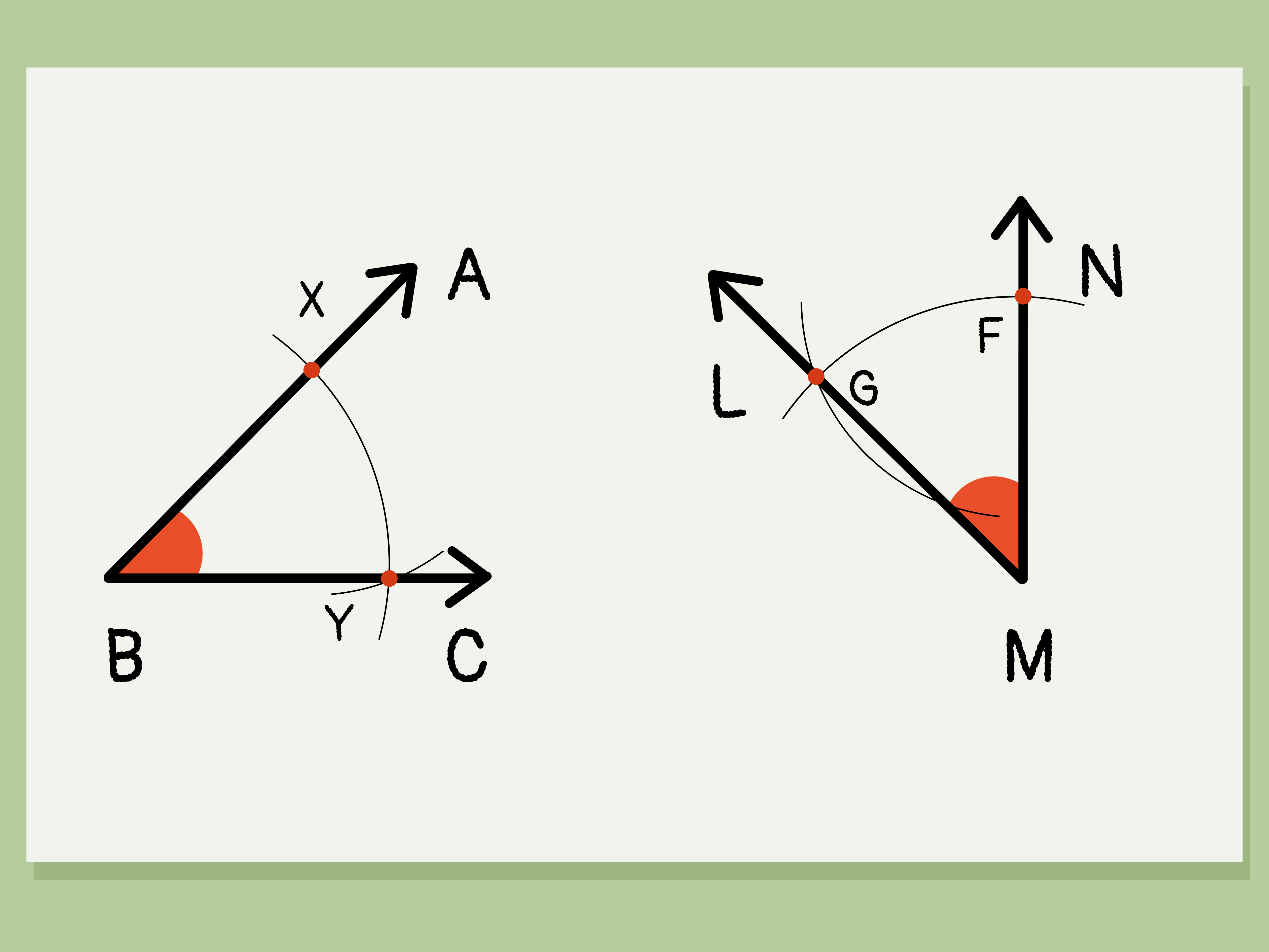
Suppose the original figure is ∠ABC, with vertex B. The goal is to create a new angle, such as ∠QPS, whose vertex is P and whose measure equals that of ∠ABC:
∠ABC ≅ ∠QPS
The congruence symbol, ≅, means “is congruent to.” Unlike drawing an angle with a protractor, a formal geometric construction does not depend on reading a numerical measurement. Instead, it transfers carefully chosen distances with a compass.
Tools You Will Need
- A compass that holds its setting securely
- An unmarked straightedge or the plain edge of a ruler
- A sharp pencil
- Paper with enough open space for two angles
- An eraser for cleaning up construction arcs afterward
A protractor is optional for checking your result, but it is not used to perform the construction. A marked ruler may serve as the straightedge, provided you do not use its scale to measure lengths. In classical construction, the straightedge draws lines while the compass transfers distances. Everyone has a job; the ruler does not get to freelance.
How to Construct an Angle Congruent to a Given Angle in 12 Steps
Begin with the given angle ∠ABC. Point B is the vertex, while rays BA and BC form its sides. You will construct the congruent angle at a new point P.
Step 1: Identify the Given Angle
Locate ∠ABC and confirm that B is its vertex. Remember that the middle letter in an angle name identifies the vertex. This small detail prevents a surprisingly large amount of geometric chaos.
Step 2: Mark the New Vertex
Choose an open area of the paper and mark a point labeled P. This point will become the vertex of the copied angle.
Step 3: Draw the New Base Ray
Use the straightedge to draw a ray beginning at P. Place another point, Q, on the ray so it can be named ray PQ. The ray may point in any convenient direction.
Step 4: Set the Compass on the Original Vertex
Place the compass point precisely on B, the vertex of the original angle. Open the compass to a convenient radius. The exact radius is unimportant, but it should be large enough to produce clear intersection points on both sides of the angle.
Step 5: Draw an Arc Across Both Original Rays
Without moving the compass point away from B, draw an arc that crosses rays BA and BC. Label the intersection on ray BA as D and the intersection on ray BC as E.
Because D and E lie on the same arc centered at B, segments BD and BE are equal radii.
Step 6: Preserve the Compass Width
Do not adjust the compass after drawing the original arc. This unchanged radius must now be transferred to the new vertex. If the compass slips, reset it using either BD or BE before continuing.
Step 7: Copy the Arc at Point P
Place the compass point on P and draw an arc that crosses ray PQ. Label that intersection R. Make the arc long enough to leave room for another intersection later.
The new arc has the same radius as the original arc, so PR equals BD and BE.
Step 8: Measure the Chord Between D and E
Now change the compass width. Place one compass point on D and open the compass until the pencil point reaches E. You are transferring the straight-line distance DE, known as a chord of the original arc.
Do not try to measure the curved portion of the arc. The required distance is the direct distance from D to Ethe tiny bridge, not the scenic route.
Step 9: Place the Compass on R
Without changing the new compass width, place its point on R, the place where the copied arc crosses ray PQ.
Step 10: Mark the Second Side of the New Angle
Draw a small arc that intersects the larger arc centered at P. Label the intersection S. Choose the intersection on the side of ray PQ where you want the new angle to open.
If the arcs intersect in two possible locations, either may produce an angle with the correct measure. The results are mirror images of each other.
Step 11: Draw the Second Ray
Align the straightedge with P and S. Draw ray PS, beginning at P and passing through S. This ray forms the second side of the copied angle.
Step 12: Label and State the Result
The completed angle is ∠QPS. State the congruence relationship clearly:
∠ABC ≅ ∠QPS
You have now copied the given angle using only a compass and straightedge. The construction works for acute, right, and obtuse angles as long as the arcs and intersections are placed accurately.
Why the Construction Works
The method is reliable because it creates two congruent triangles: triangle BDE inside the original angle and triangle PRS inside the copied angle.
- BD = PR: Both were drawn using the same compass radius.
- BE = PS: These are also radii of arcs drawn with that unchanged setting.
- DE = RS: The chord DE was transferred directly to the second arc.
All three corresponding sides of triangles BDE and PRS are equal. Therefore, the triangles are congruent by the Side-Side-Side Congruence Theorem, commonly abbreviated as SSS.
Corresponding angles in congruent triangles are congruent. Consequently, the angle between BD and BE equals the angle between PR and PS. Since D lies on ray BA, E lies on ray BC, and R lies on ray PQ, those angles are the original and copied angles:
∠ABC ≅ ∠QPS
This proof also explains why the radius chosen in Step 4 does not determine the angle’s measure. A larger radius creates a larger helper triangle, while a smaller radius creates a smaller one. The transferred chord preserves the same shape and therefore the same opening.
A Specific Example
Imagine that ∠ABC measures 67 degrees, although you are not told that number. Following the construction transfers the arc radius and its chord to point P. The resulting ∠QPS will also measure 67 degrees.
You could rotate the new base ray, move the new vertex across the page, or draw the angle as a mirror image. Its position and orientation would change, but its measure would remain 67 degrees. Congruence concerns size, not which direction the angle happens to be looking.
Common Mistakes and How to Fix Them
Changing the First Compass Setting
The original arc and the arc centered at P must have equal radii. If you alter the compass width between them, the two helper triangles may no longer be congruent. Lock the compass if possible, or handle it near the hinge rather than squeezing its legs.
Copying the Arc Length Instead of the Chord
The second measurement is the straight distance DE, not the length of the curved arc from D to E. Place the compass points directly on D and E.
Using the Wrong Point as the Vertex
For ∠ABC, the vertex is B because it is the middle letter. Centering the first arc at A or C copies something, certainly, but not the angle requested.
Making Arcs Too Short
The arc centered at P must be long enough to intersect the small arc drawn from R. Extending it generously is easier than searching for an intersection that exists just beyond your pencil mark.
Drawing Thick or Fuzzy Lines
Wide pencil marks make exact intersections difficult to identify. Use a sharp pencil, light pressure, and a small dot at each required intersection.
Confusing Congruence With Similarity
Congruent angles have equal measures. Their rays do not need equal visible lengths because rays theoretically extend forever. Longer pencil lines do not create larger angles.
Choosing the Unexpected Intersection
If you mark S on the opposite side of the base ray, the result may be a reflected version of the intended drawing. It is still congruent, but it may not match the requested orientation. Check which side of ray PQ the new angle should occupy before drawing ray PS.
Can You Check the Result With a Protractor?
Yes. After completing the formal construction, measure both angles with a protractor as a practical check. Their readings should be equal or extremely close.
A small discrepancy usually comes from pencil thickness, a loose compass, or inaccurate placement rather than a flaw in the geometric method. The theoretical construction is exact; physical drawing tools merely do their best impression of perfection.
What About Reflex Angles?
The standard procedure naturally identifies the smaller angle between two rays, usually an angle from 0 to 180 degrees. If the given figure specifically indicates a reflex angle greater than 180 degrees, first copy the smaller angle and then designate the exterior region as the reflex angle.
For example, if the smaller opening is 110 degrees, the corresponding reflex angle is 360 − 110, or 250 degrees. The same pair of rays defines both regions, so the diagram must clearly show which region is intended.
Where Congruent-Angle Construction Is Used
Copying an angle is more than an isolated worksheet exercise. It supports several important geometric constructions and forms of reasoning:
- Constructing a line parallel to a given line through an exterior point
- Reproducing triangles from specified sides and angles
- Creating repeated patterns, polygons, and geometric designs
- Understanding corresponding angles and rigid transformations
- Building formal proofs involving triangle congruence
- Developing accurate drafting and technical-drawing habits
The technique also illustrates a broader mathematical principle: an angle can be reproduced by preserving relationships among distances. No numerical angle measurement is required.
Practical Experiences and Lessons From Constructing Congruent Angles
The first attempt at copying an angle often looks more complicated than the finished idea deserves. The page fills with arcs, labels, and tiny intersections, and it can feel as though the compass has started making decisions independently. In practice, the task becomes much easier once the marks are understood as two separate transfers.
The first transfer copies the radius from the original vertex to the new vertex. The second transfers the chord between the original angle’s sides. Remembering “radius first, chord second” is far more useful than memorizing a long paragraph of directions.
Start With a Comfortable Angle
For early practice, a medium-sized acute or obtuse angle is usually easier than a very narrow one. If the angle is extremely small, points D and E sit close together, making the chord difficult to capture accurately. If the angle is nearly straight, the drawing may demand more paper than expected. An angle around 60 to 120 degrees provides clear, well-separated points.
Give the Drawing Room to Breathe
A common practical failure begins before the compass touches the page: point P is placed too close to an edge. Then the copied arc runs off the paper, ray PS collides with the margin, and geometry turns into an unplanned stationery crisis. Placing the new vertex near the center of an open area avoids this problem.
Use Light Construction Marks
Light arcs are easier to refine and erase. The final rays can be darkened after the correct intersection is confirmed. Heavy arcs may hide the exact point where they cross, while a sharp pencil creates a small, reliable target.
Handle the Compass Deliberately
Accuracy improves when the compass is rotated from the top rather than pushed sideways by one leg. Side pressure can alter the radius while the arc is being drawn. It also helps to pause after placing the needle and confirm that it is centered exactly on the labeled point.
A loose compass creates inconsistent arcs even when every written step is followed correctly. Tightening its hingeor replacing a particularly rebellious classroom compasscan solve what initially appears to be a misunderstanding of geometry.
Label Points as Soon as They Appear
Waiting until the end to label D, E, R, and S makes the construction harder to explain and easier to misread. Immediate labels turn a collection of marks into a logical sequence. They are especially helpful when writing the SSS proof, because each transferred length can be identified without detective work.
Check the Logic Before Checking the Number
A protractor can confirm that the final measures are close, but it should not replace reasoning. First ask whether the two main arcs used the same radius and whether DE was transferred to RS. If both conditions are satisfied, the mathematical argument is complete.
This distinction is an important part of the learning experience. Measurement says the angles appear equal within the accuracy of the instrument. Construction and proof explain why they must be equal.
Practice With Different Orientations
After succeeding once, draw the base ray pointing left, upward, or diagonally. Then construct the copy on either side of it. This practice reinforces that the direction and visible ray lengths do not determine angle size.
Eventually, the forest of arcs stops looking like clutter. Each mark records a preserved distance, and the procedure becomes a compact lesson in how geometric proof and physical drawing support each other.
Conclusion
To construct an angle congruent to a given angle, copy one arc radius, transfer the chord between the original angle’s sides, and draw a ray through the resulting intersection. These actions create two SSS-congruent triangles, proving that the original and constructed angles have equal measures.
The process rewards careful compass handling more than speed. Keep the first radius unchanged, transfer the chord accurately, and use clean intersection points. With a little practice, the 12 steps shrink into one memorable idea: copy the radius, copy the chord, and connect the dots.