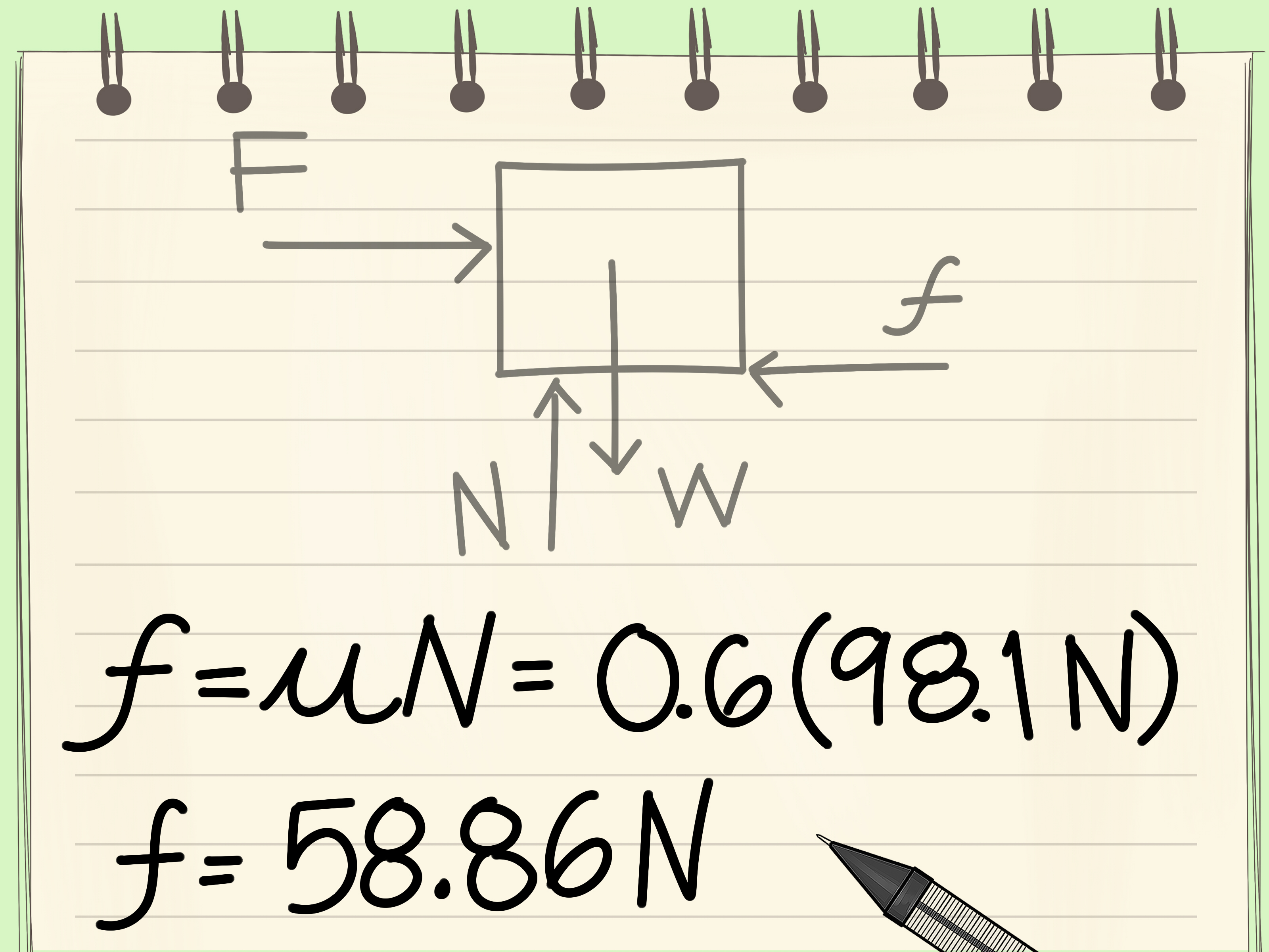

A free body diagram can turn a crowded physics problem into a small collection of manageable arrows. That may not sound glamorous, but neither is staring at an equation for twenty minutes while wondering where the normal force went.
Also called an FBD or force diagram, a free body diagram isolates one object or system and shows every external force acting on it. It provides the visual foundation for applying Newton’s laws, calculating acceleration, testing equilibrium, and solving statics or dynamics problems.
This guide explains how to draw a free body diagram in 10 practical steps. Along the way, you will learn how to identify forces, choose useful coordinate axes, handle friction and inclined planes, label vectors correctly, and avoid the mistakes that make physics homework considerably more dramatic than necessary.
What Is a Free Body Diagram?
A free body diagram is a simplified drawing of an isolated object and the external forces acting on it. The object may be represented by a dot, box, or recognizable outline. Each force appears as a labeled vector with a direction and, when known, a magnitude.
The word “free” means the body has been conceptually separated from its surroundings. A table, rope, wall, hinge, spring, or neighboring object is removed from the sketch and replaced by the force it exerts on the selected body.
A standard FBD may include:
- Weight or gravitational force
- Normal force from a supporting surface
- Static or kinetic friction
- Tension from a rope, string, or cable
- Applied pushes and pulls
- Spring force
- Drag, air resistance, buoyancy, or thrust
- Support reactions and moments in engineering problems
Velocity, acceleration, and the path of motion are useful information, but they are not forces. They may be shown beside an FBD as reference annotations, but they should not masquerade as force arrows wearing fake mustaches.
How to Draw a Free Body Diagram in 10 Steps
Step 1: Read the Entire Problem
Begin by reading the complete problem before drawing anything. Identify what is happening, which quantities are known, and what must be calculated. Look for words such as “resting,” “accelerating,” “sliding,” “hanging,” “constant speed,” or “about to move.” These clues affect the equations you will eventually write.
Do not assume that motion and force point in the same direction. A ball traveling upward after leaving a hand, for example, can have an upward velocity while gravity acts downward. The hand is no longer touching the ball, so the hand’s force does not belong on the ball’s free body diagram.
Step 2: Select the Body or System of Interest
Decide exactly what object or group of objects you are analyzing. This choice defines the boundary of the free body. If the problem involves two blocks connected by a rope, you might analyze each block separately or treat both blocks as one system.
Separate diagrams are useful when you need the tension or contact force between objects. A combined-system diagram can simplify calculations because forces exchanged internally between the included objects do not appear.
Write the selected body’s name above the sketch. A label such as “block A” or “cart-plus-load system” prevents confusion when several diagrams begin multiplying across the page.
Step 3: Isolate and Simplify the Body
Draw the chosen body away from its surroundings. A dot is usually enough for particle mechanics, while a box or outline is better when the point of application, rotation, torque, or dimensions matter.
Remove the floor, rope, wall, ramp, and other neighboring objects from the isolated drawing. You will replace each relevant interaction with a force vector. The goal is not artistic realism. If your block looks like an unusually confident potato, the laws of physics will survive.
Step 4: Identify Every External Interaction
Ask what objects in the environment interact with the selected body. A useful method is to divide forces into two categories:
- Long-range forces: Gravity, electric forces, and magnetic forces can act without direct physical contact.
- Contact forces: Normal force, friction, tension, spring force, drag, and applied force require an interaction with another object or material.
For a book resting on a table, Earth exerts the book’s weight downward and the table exerts a normal force upward. The book also pushes down on the table, but that force acts on the table, not on the book. Therefore, it belongs on the table’s FBD rather than the book’s.
Step 5: Draw the Weight Force
Near Earth’s surface, weight has a magnitude of:
W = mg
Here, m is mass and g is gravitational acceleration, approximately 9.8 m/s2. Draw the weight vector vertically downward, regardless of whether the body rests on a flat surface, hangs from a rope, or sits on an incline.
For particle models, the arrow begins at the dot representing the object. In rigid-body diagrams, weight is commonly applied at the center of gravity. Do not tilt the weight vector to match an inclined plane. Gravity remains stubbornly vertical.
Step 6: Add Contact and Applied Forces
Replace every removed contact with the appropriate force:
- Normal force: Acts perpendicular to the contact surface and away from it.
- Friction: Acts parallel to the surface and opposes actual or impending relative motion.
- Tension: Pulls along a rope, cable, or string and away from the body.
- Spring force: Acts along the spring and opposes stretching or compression.
- Applied force: Points in the direction of the external push or pull.
- Drag: Generally opposes motion relative to the surrounding fluid.
Do not automatically set the normal force equal to the object’s weight. That equality applies only in certain situations, such as a body on a horizontal surface with no other vertical acceleration or vertical force components.
Step 7: Choose a Convenient Coordinate System
Add coordinate axes after identifying the forces. On a level surface, horizontal and vertical axes are usually convenient. On an inclined plane, rotate the axes so the x-axis runs parallel to the slope and the y-axis runs perpendicular to it.
The forces themselves do not rotate when you rotate the coordinate system. Instead, you resolve angled forces into components along the selected axes. Choosing helpful axes reduces trigonometric clutter and lowers the risk of a surprise sine-versus-cosine wrestling match.
Step 8: Draw, Size, and Label the Force Vectors
Draw each force as an arrow originating on the isolated body. The arrowhead shows direction, while its length may indicate relative magnitude when the relationship is known. Label every vector clearly using consistent notation, such as:
- W or Fg for weight
- N or FN for normal force
- fs for static friction
- fk for kinetic friction
- T for tension
- Fapp for an applied force
Unknown magnitudes should receive symbols rather than invented numerical values. Include important angles, distances, or points of application when they will be needed for components or torque calculations.
Step 9: Resolve Angled Forces Into Components
If a force does not lie along one coordinate axis, break it into perpendicular components. For a force F making an angle θ with the positive x-axis:
Fx = F cos θ
Fy = F sin θ
On an incline of angle θ, the weight components are commonly:
Wparallel = mg sin θ
Wperpendicular = mg cos θ
You can show the original vector or its components in the working diagram, but avoid counting both in the force equations. Otherwise, gravity effectively receives a duplicate vote.
Step 10: Check the Diagram and Write the Equations
Before calculating, audit the completed free body diagram. Confirm that:
- Only forces acting on the selected body are shown.
- Every external interaction has been represented.
- Each arrow has the correct direction and label.
- No velocity, acceleration, or “force of motion” appears as a force.
- The coordinate axes and necessary angles are clear.
- Internal forces are excluded when analyzing a combined system.
Translate the diagram into Newton’s second-law equations:
ΣFx = max
ΣFy = may
For static equilibrium or constant velocity, acceleration is zero, so the net force in each direction is zero. Rigid-body equilibrium may also require the moment equation ΣM = 0.
Worked Example: A Block on an Inclined Plane
Consider a 5.0-kilogram block resting on a frictionless ramp inclined at 30 degrees. The selected body is the block. Once isolated, it has two external forces: its weight acting vertically downward and the ramp’s normal force acting perpendicular to the surface.
The block’s weight is:
W = mg = (5.0 kg)(9.8 m/s2) = 49 N
Choose the x-axis parallel to the ramp and the y-axis perpendicular to it. Resolve the weight:
Wparallel = 49 sin 30° = 24.5 N
Wperpendicular = 49 cos 30° ≈ 42.4 N
There is no acceleration perpendicular to the ramp, so the normal force balances the perpendicular component of weight:
N = 42.4 N
Along the frictionless ramp, the net force is 24.5 N downhill. Therefore:
a = Fnet/m = 24.5 N/5.0 kg = 4.9 m/s2
Notice that the normal force is not 49 N. It balances only the portion of weight pressing the block into the incline.
Common Free Body Diagram Mistakes
Including Forces Exerted by the Body
An FBD shows forces acting on the selected object, not forces that object exerts on something else. Newton’s third-law partner forces act on different bodies and therefore belong on different diagrams.
Drawing a Force in the Direction of Motion
An object does not require a forward force merely because it moves forward. If a puck slides across nearly frictionless ice at constant velocity, its horizontal net force can be zero.
Adding “Net Force” as Another Arrow
Net force is the vector sum of the individual forces. It is a result, not an additional interaction. Draw the actual forces and calculate their resultant afterward.
Assuming Friction Always Equals μN
Kinetic friction is commonly modeled as fk = μkN. Static friction, however, adjusts up to a maximum value: fs ≤ μsN. A stationary object does not automatically experience maximum static friction.
Mixing Multiple Bodies Into One Unclear Sketch
When analyzing connected objects individually, draw a separate FBD for each one. If you intentionally choose the entire group as the system, omit forces that are internal to that system.
Practical Experiences and Lessons From Drawing FBDs
One of the most common experiences among beginning physics students is believing that the equations are the difficult part. After several assignments, many discover that the real challenge happens earlier: deciding which forces belong in the equations. A correct free body diagram often makes the algebra almost routine; an incorrect diagram produces beautifully organized nonsense.
A useful classroom habit is the “interaction inventory.” Before drawing arrows, list everything that touches or influences the object. For a crate pulled across a floor, the inventory might include Earth, the floor, and the rope. Those three interactions suggest weight, a normal force, friction, and tension. This method is especially valuable when a diagram contains distracting details such as people, pulleys, vehicles, or decorative scenery.
Inclined-plane problems offer another memorable lesson. Students frequently rotate gravity so it points perpendicular to the ramp. The mistake feels natural because the page has been mentally rotated, but gravity has not signed the paperwork. Drawing the vertical weight vector first and choosing tilted axes afterward usually prevents the error.
It also helps to delay numerical substitution. Keeping expressions such as mg sin θ and mg cos θ visible makes the physical relationships easier to inspect. Symbolic work reveals how changing the mass or ramp angle affects the result and reduces repeated calculator work.
Ropes and pulleys teach the importance of specifying the system. A two-block setup may look like one problem, but it can require three useful diagrams: one for each block and one for the combined system. The individual diagrams reveal tension; the combined diagram often makes acceleration easier to find because tension becomes internal and cancels.
Friction problems produce their own collection of “aha” moments. Static friction is not automatically equal to its maximum possible value. If a 10-newton horizontal push is balanced by static friction, the friction force is 10 newtonsas long as the required amount stays below the limiting value. The surface does not deploy maximum friction simply because it is feeling enthusiastic.
In engineering statics, the quality of an FBD becomes even more important. Support reactions, applied moments, dimensions, and points of application must be shown carefully. Replacing a support with the wrong reaction components can make an equilibrium problem impossible to solve or produce more unknowns than available equations.
A final practical lesson is to redraw messy diagrams. Students sometimes treat their first sketch as sacred, even after arrows overlap and labels become unreadable. Starting a clean version takes less time than debugging crowded work. A successful force diagram should be understandable at a glance: one system, clear axes, labeled vectors, and no mystery arrows wandering around without identification.
Conclusion
Learning how to draw a free body diagram is fundamentally about learning how to see interactions. Select one object or system, isolate it, replace its surroundings with external forces, choose convenient axes, and check the completed diagram before writing equations.
With practice, FBDs become more than a classroom requirement. They provide a dependable problem-solving language for Newton’s laws, friction, tension, inclined planes, connected bodies, equilibrium, structural supports, and many other mechanics topics. Keep the diagram simple, but make the thinking precise. In physics, a few accurate arrows can save an impressive amount of algebraic suffering.